
T beam in-situ bracket method prefabrication method

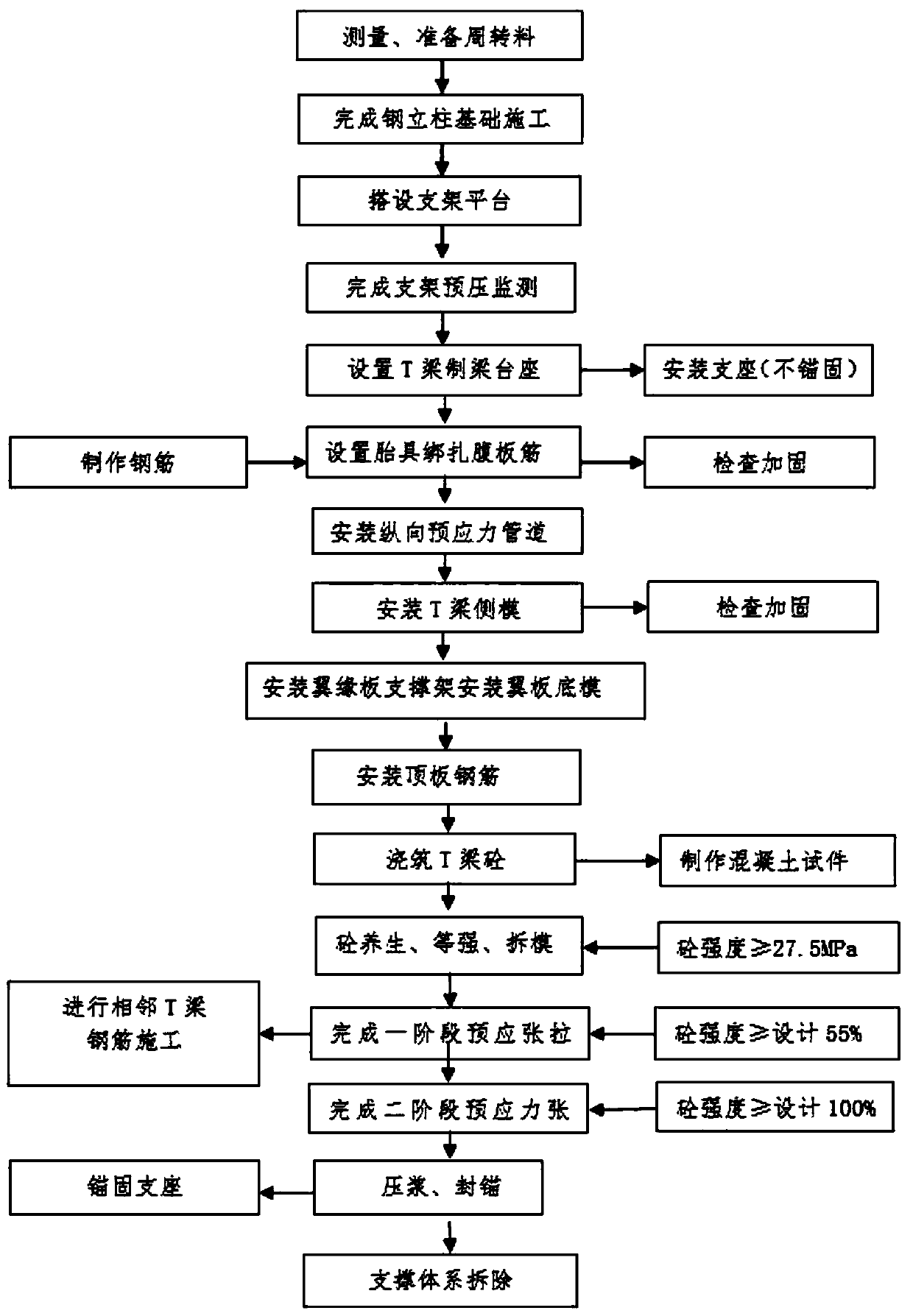
A construction method and in-situ technology, applied in the field of T-beam in-situ support method prefabrication construction method, can solve the problems of increased beam field construction and reclamation, high cost of entry and exit, and high safety risk of T-beam transportation, so as to avoid the risk of overturning Effect

Inactive Publication Date: 2019-10-25
ROAD & BRIDGE ENG CO LTD OF CHINA RAILWAY SEVENTH GRP
View PDF5 Cites 3 Cited by
  • Summary
  • Abstract
  • Description
  • Claims
  • Application Information

AI Technical Summary

Problems solved by technology

For engineering projects that do not have the site selection conditions for the beam yard near the construction site, the site selection planning for the beam yard needs to be carried out in a remote place. The T-beam needs to be transported over tens of miles through urban roads to reach the construction site. Some T-beam spans are relatively large, but the number of projects is small. The use of traditional construction methods has the disadvantages of high consumption of beam yard construction, high safety risks of T-beam transportation, and large-scale equipment such as large-tonnage bridge erecting machines. The construction and reclamation of farms have increased the pressure on the environment and many other disadvantages.

Method used


Image

  • T beam in-situ bracket method prefabrication method

Examples


Embodiment Construction

[0021] In order to make the technical means, creative features, goals and effects of the present invention easy to understand, the present invention will be further elaborated below in conjunction with specific illustrations. In the description of the present invention, it should be noted that unless otherwise specified and Limitation, the terms "installation", "connection" and "connection" should be understood in a broad sense, for example, it can be a fixed connection, it can also be a detachable connection, or an integral connection can be a mechanical connection or an electrical connection; it can be It can be directly connected, or indirectly connected through an intermediary, and can be connected internally between two components.

[0022] Such as figure 1 As shown, a T-beam in-situ support method prefabrication method includes the following steps:

[0023] Step (1). Measure and prepare turnover materials;

[0024] Step (2). Complete the steel column foundation constru...


PUM


Abstract

The invention provides a T beam in-situ bracket method prefabrication method, comprising the following steps: step (1), measuring and preparing a turnover material; step (2), completing the foundationconstruction of a steel column and setting up a support platform; step (3), completing the pre-pressure monitoring of a bracket, arranging a T-beam fabricating pedestal, and installing a support; step (4), setting a clamping fixture to bind web ribs; step (5), installing a longitudinal prestressed pipeline; step (6), installing a flange plate supporting bracket and a flange plate; step (7), concrete pouring, maintaining, strengthening and demolding; step (8), grouting, sealing anchors, anchoring supports, and finally removing a support system. Compared with the prefabrication and transportation of a beam field, and erecting of a bridge erecting machine, the method avoids the risk of overturning in the long-distance T-beam transportation, reduces the use and process management of large equipment such as gantry cranes and the bridge erecting machines, and is not affected by adjacent hole spanning transport corridors. The method can be completed by using conventional cranes, transportation equipment and concrete supply equipment.

Description

technical field [0001] The invention relates to the technical field of engineering construction, in particular to a prefabrication method of a T-beam in-situ support method. Background technique [0002] With the improvement of municipal bridge construction technology, bridge projects that routinely use T-beams as the superstructure are all prefabricated in the prefabricated beam yard, transported to the construction site by beam trucks, and then erected by bridge erecting machines. For engineering projects that do not have the site selection conditions for the beam yard near the construction site, the site selection planning for the beam yard needs to be carried out in a remote place. The T-beam needs to be transported over tens of miles through urban roads to reach the construction site. Some T-beam spans are relatively large, but the number of projects is small. The use of traditional construction methods has the disadvantages of high consumption of beam yard construction...

Claims


Application Information

Patent Timeline
IPC IPC(8): E01D21/00E01D2/00E01D101/28
CPCE01D2/00E01D21/00E01D2101/28
Inventor 刘永勤徐洪流严占华杨通李永康张文利
Owner ROAD & BRIDGE ENG CO LTD OF CHINA RAILWAY SEVENTH GRP
Learn More