Automatic lubricating oil injection device

An oil injection equipment and automatic lubrication technology, applied in the direction of engine lubrication, lubricating oil control valve, mechanical equipment, etc., can solve the problems of slow lubricating oil injection speed, low oil injection efficiency, mechanical equipment consequences, etc. The effect of burden and loss avoidance

Active Publication Date: 2019-10-25
上海泽煦智能科技有限公司
View PDF9 Cites 0 Cited by
  • Summary
  • Abstract
  • Description
  • Claims
  • Application Information

AI Technical Summary

Problems solved by technology

[0002] The oiling equipment is mainly used for oiling the various parts of the driver; the existing oiling equipment mainly relies on the oiling system to directly oil the parts of the disassembled driver, but because the driver needs to be disassembled to form multiple parts before oiling, now There are technologies to manually inject lubricating oil on a regular basis. If it is not injected within the specified time, it will have serious consequences for mechanical equipment.
[0003] Chinese patent CN207065039U discloses a leak-proof oiling equipment. The parts obtained after the driver is disassembled are respectively placed on the oiling tool. Move between the oiling position and the oiling position; the camera mechanism is located above the preparatory position and is connected with the frame, and is used to take pictures of the parts in the preparatory position; the oiling system is connected with the machine table, and performs various parts in the oiling position Oil injection; however, during the oil injection process of this device, the injection speed of lubricating oil is slow, resulting in low oil injection efficiency. Therefore, we propose an automatic lubrication oil injection equipment

Method used


Image

  • Automatic lubricating oil injection device
  • Automatic lubricating oil injection device
  • Automatic lubricating oil injection device

Examples


Embodiment 1

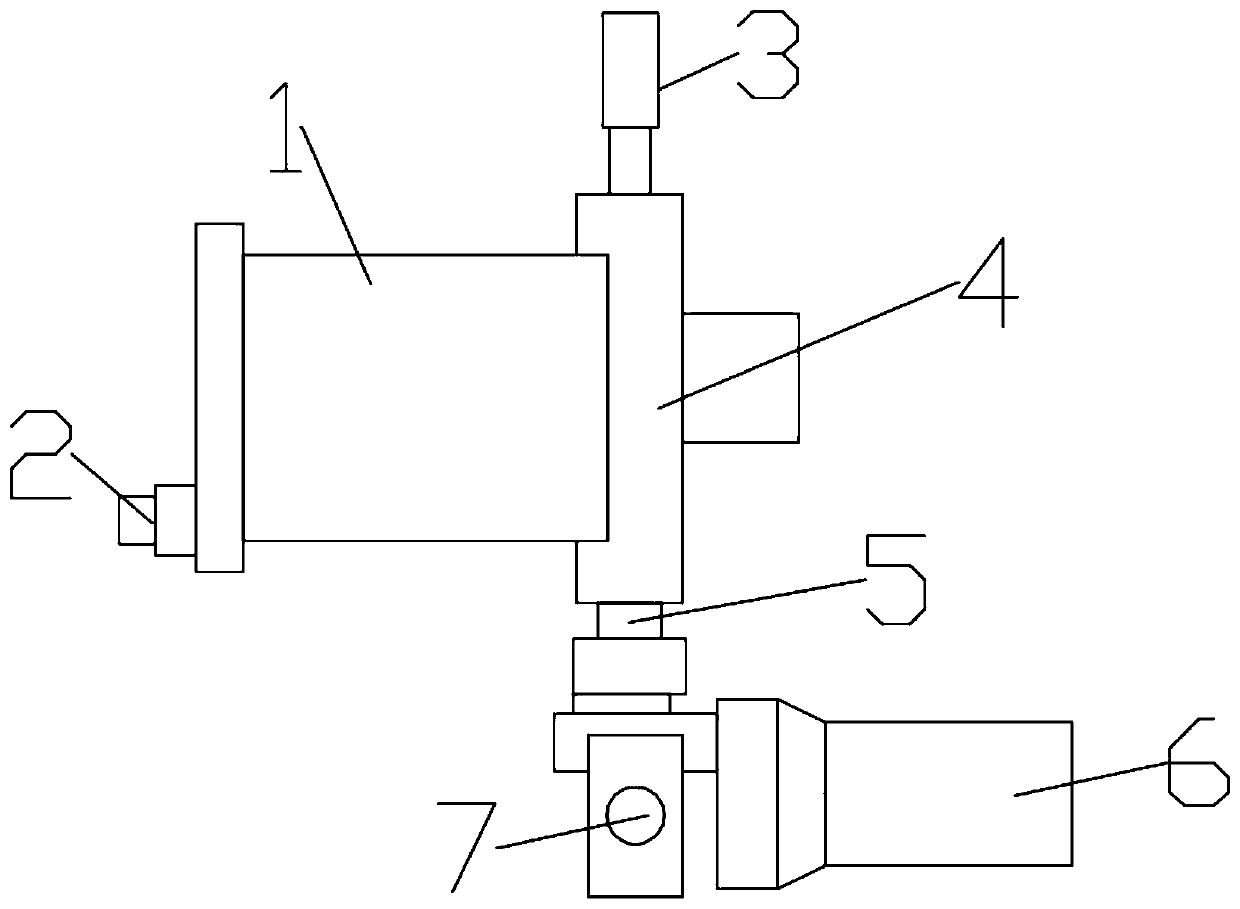
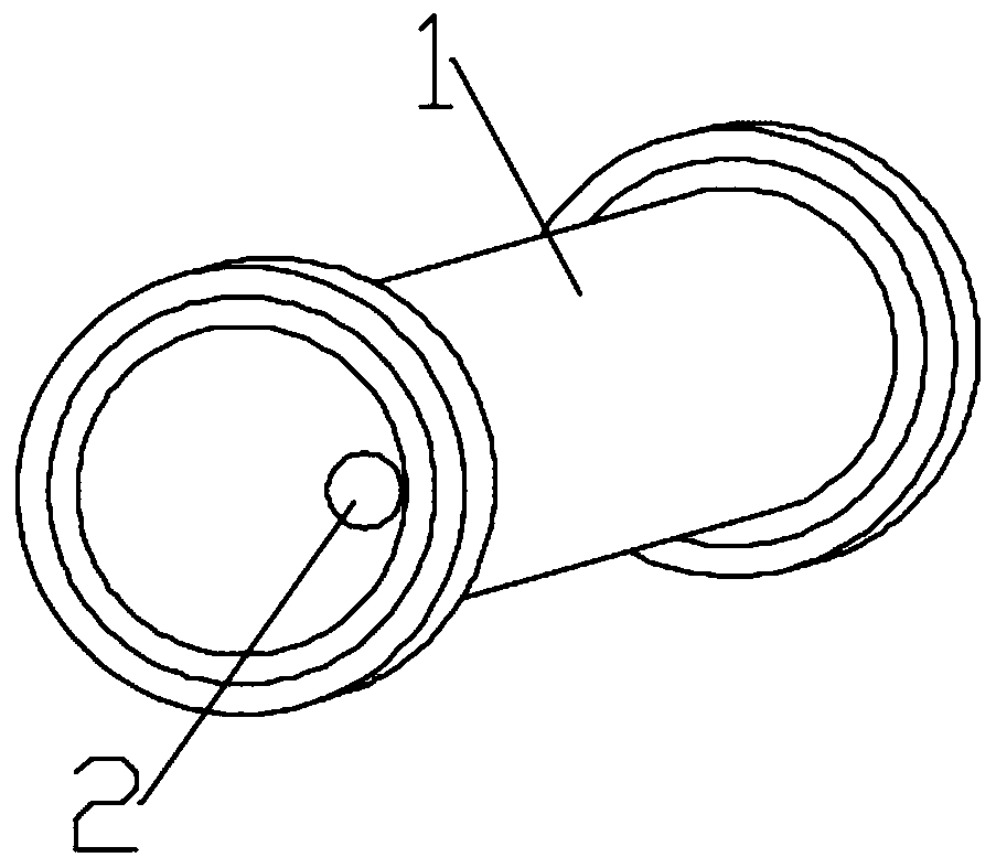
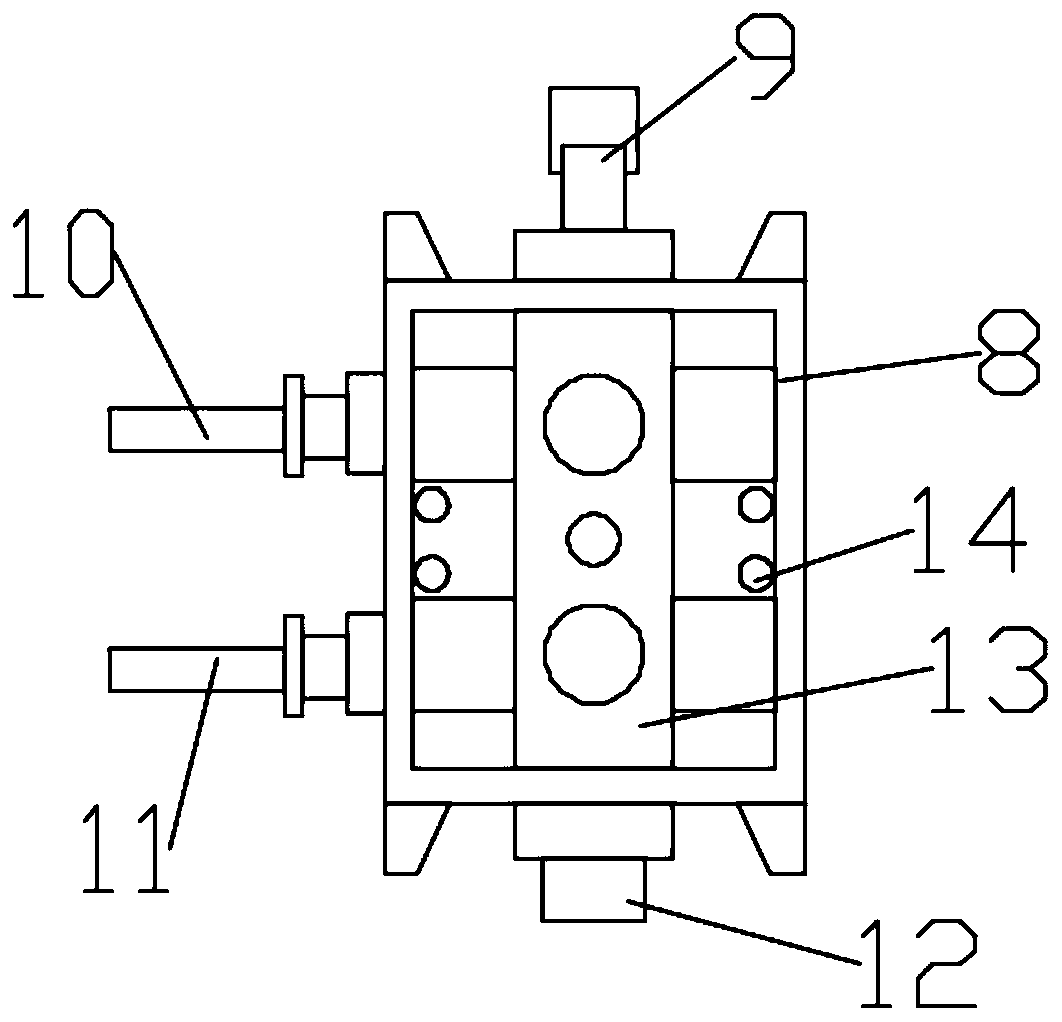
[0020] Such as Figure 1~5 As shown, in the embodiment of the present invention, an automatic lubricating oil injection device includes an oil injection chamber 1 and a pressurized assembly, the oil injection chamber 1 is provided with an oil injection assembly 8 for automatic oil injection, and the oil injection assembly 8 is fixedly installed on the oil injection assembly On the installation seat 14, the oil injection assembly installation seat 14 is fixedly installed on the inner wall of the oil injection chamber 1 by bolts, the oil injection chamber 1 is fixed on the oil injection chamber installation seat 4, and a pressurization assembly is connected below the oil injection chamber 1;

[0021] The pressurization assembly includes a pressure regulating valve 6, a pneumatic valve and an air pump. The air pump is an existing technology and is not limited here. A pneumatic valve is installed on the air pump, and the air pump communicates with the pressure regulating valve 6, a...

Embodiment 2

[0025] Such as Figure 1~5 As shown, in the embodiment of the present invention, an automatic lubricating oil injection device includes an oil injection chamber 1 and a pressurized assembly, the oil injection chamber 1 is provided with an oil injection assembly 8 for automatic oil injection, and the oil injection assembly 8 is fixedly installed on the oil injection assembly On the installation seat 14, the oil injection assembly installation seat 14 is fixedly installed on the inner wall of the oil injection chamber 1 by bolts, the oil injection chamber 1 is fixed on the oil injection chamber installation seat 4, and a pressurization assembly is connected below the oil injection chamber 1;

[0026] The pressurization assembly includes a pressure regulating valve 6, a pneumatic valve and an air pump. The air pump is an existing technology and is not limited here. A pneumatic valve is installed on the air pump, and the air pump communicates with the pressure regulating valve 6, a...


PUM


Abstract

The invention discloses an automatic lubricating oil injection device, and belongs to the technical field of oil injection devices. The problem that an existing device is low in lubricating oil injection speed is solved. According to the technical scheme, the device comprises an oil injection cavity and a pressurizing assembly, an oil injection assembly used for automatic oil injection is arrangedin the oil injection cavity, the oil injection assembly is fixedly mounted on an oil injection assembly mounting base, the oil injection assembly mounting base is fixedly arranged on the inner wall of the oil injection cavity through a bolt, the oil injection cavity is fixed to the oil injection cavity mounting base, the pressurizing assembly is connected below the oil injection cavity, the oil injection cavity is connected with a grease detector used for detecting grease, lubricating oil can be automatically added, the damage to equipment due to lacking of the lubricating oil can be avoided,meanwhile, operation is easy, the failure rate is low, the oil injection speed is high, and the efficiency is high.

Description

technical field [0001] The invention relates to the technical field of oil injection equipment, in particular to an automatic lubricating oil injection equipment. Background technique [0002] The oiling equipment is mainly used for oiling the various parts of the driver; the existing oiling equipment mainly relies on the oiling system to directly oil the parts of the disassembled driver, but because the driver needs to be disassembled to form multiple parts before oiling, now There are technologies that regularly inject lubricating oil manually. If it is not injected within the specified time, it will have serious consequences for mechanical equipment. [0003] Chinese patent CN207065039U discloses a leak-proof oiling equipment. The parts obtained after the driver is disassembled are respectively placed on the oiling tool. Move between the oiling position and the oiling position; the camera mechanism is located above the preparatory position and is connected with the frame...

Claims


Application Information

Patent Timeline
Patent Type & Authority Applications(China)
IPC IPC(8): F16N7/38F16N23/00
CPCF16N7/38F16N23/00
Inventor 胡志勇
Owner 上海泽煦智能科技有限公司
Why Eureka
Try Eureka