Multifunctional furnace
A multi-functional, furnace bar technology, which is applied in the direction of steam boilers, steam boiler accessories, steam boiler components, etc., can solve the problems of single heating form, uneven heating effect, and large heat loss of the heating furnace, and achieve sufficient and reasonable The effect of energy utilization, flexible handling, and increased heating area
- Summary
- Abstract
- Description
- Claims
- Application Information
AI Technical Summary
Problems solved by technology
Method used
Image
Examples
Embodiment 1
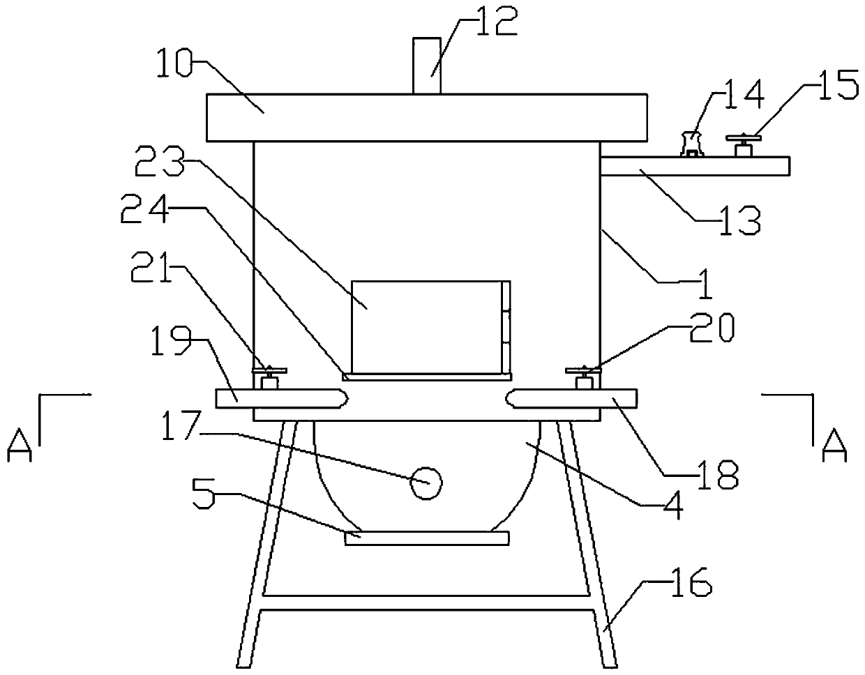
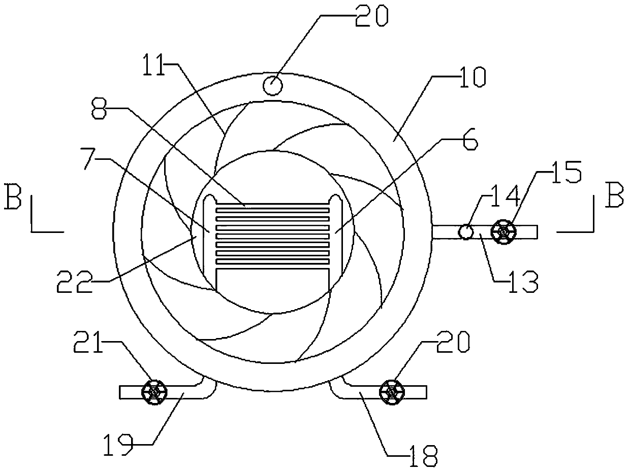
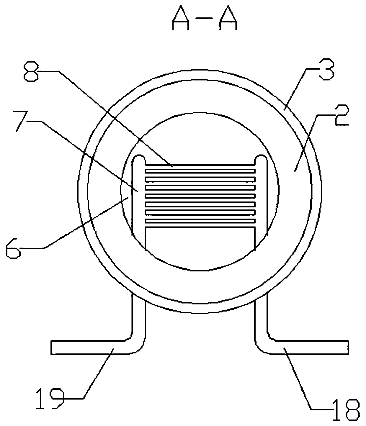
[0021] A multifunctional furnace includes a furnace body 1, an ash chamber 4, a water vapor circulation system and a combustion chamber 9. The water vapor circulation system includes a water inlet pipe 18 , a water jacket 2 , a water inlet connection pipe 6 , a water passage bar 8 , a water outlet connection pipe 7 , a water outlet pipe 19 and a steam pipe 13 . The water jacket 2 is arranged on the inner circumference of the furnace body 1, the water jacket 2 surrounds the combustion chamber 9, and the water-through furnace bar 8 is arranged on the combustion chamber 9 and the ash chamber 4 Between them, the water-through furnace bars 8 are arranged side by side, and the two ends of the water-through furnace bars 8 communicate with the water inlet connecting pipe 6 and the water outlet connecting pipe 7; the water inlet pipe 18 communicates with the outer wall of the water jacket 2, so that The inner wall of the water jacket 2 communicates with the water inlet end of the water...
Embodiment 2
[0023] The difference between this embodiment and Embodiment 1 is that: the water inlet connecting pipe 6 and the water outlet connecting pipe 7 are fixed on the inner wall of the combustion chamber 9 through the fixing piece 22; the water inlet pipe 18 is provided with a water inlet valve 20, so The water outlet pipe 19 is provided with a water outlet valve 21, and the water flow rate and the liquid level in the water jacket 2 are controlled by the water inlet valve 20 and the water outlet valve 21; and the height of the water outlet connecting pipe 7 are flush with the bottom of the water jacket 2, water enters the water jacket 2 from the water inlet pipe 18, and the water in the water jacket 2 flows into the water inlet connecting pipe 6, the water flow bar 8 and the water outlet successively. Connecting pipe 7, water enters the water jacket 2 after coming out of the water outlet connecting pipe 7, and then flows out through the water outlet connecting pipe 7.
Embodiment 3
[0025] The difference between this embodiment and Embodiment 1 is: the steam pipe 13 is provided with a steam valve 15 and an air pressure valve 14, the air pressure valve 14 is arranged on the side near the furnace body 1, and the steam valve 15 controls the output of steam; When the air pressure exceeds a certain value, the air pressure valve 14 will jump up to remind the operator to deflate. The air pressure valve 14 can directly recycle the old pressure cooker air valve, which is more environmentally friendly and saves costs.
[0026] Working process: Mode 1: Before burning the furnace, close the water outlet valve 21, open the water inlet valve 20 and the steam valve 15, inject water into the water inlet pipe 18, the water jacket 2, the water inlet connection pipe 6, the water furnace bar 8, and the water outlet connection In the pipe 7 and the water outlet pipe 19; start the furnace, close the water inlet valve 20 and the steam valve 15, after the water is boiled, the wa...
PUM
 Abstract
Description
Claims
Application Information
 - R&D
- Intellectual Property
- Life Sciences
- Materials
- Tech Scout
- Unparalleled Data Quality
- Higher Quality Content
- 60% Fewer Hallucinations
Browse by: Latest US Patents, China's latest patents, Technical Efficacy Thesaurus, Application Domain, Technology Topic, Popular Technical Reports.
© 2025 PatSnap. All rights reserved.Legal|Privacy policy|Modern Slavery Act Transparency Statement|Sitemap|About US| Contact US: help@patsnap.com


