
A temperature control cover for a space optical mirror

A technology of space optics and mirrors, which is applied in optics, optical components, temperature control, etc., can solve problems such as insufficient temperature control accuracy, reduced shooting accuracy, and mirror deformation, so as to reduce deformation, reduce deformation, and reduce heat loss. Delivery rate consistent effect

Active Publication Date: 2021-03-19
CHANGCHUN INST OF OPTICS FINE MECHANICS & PHYSICS CHINESE ACAD OF SCI
View PDF4 Cites 0 Cited by
  • Summary
  • Abstract
  • Description
  • Claims
  • Application Information

AI Technical Summary

Problems solved by technology

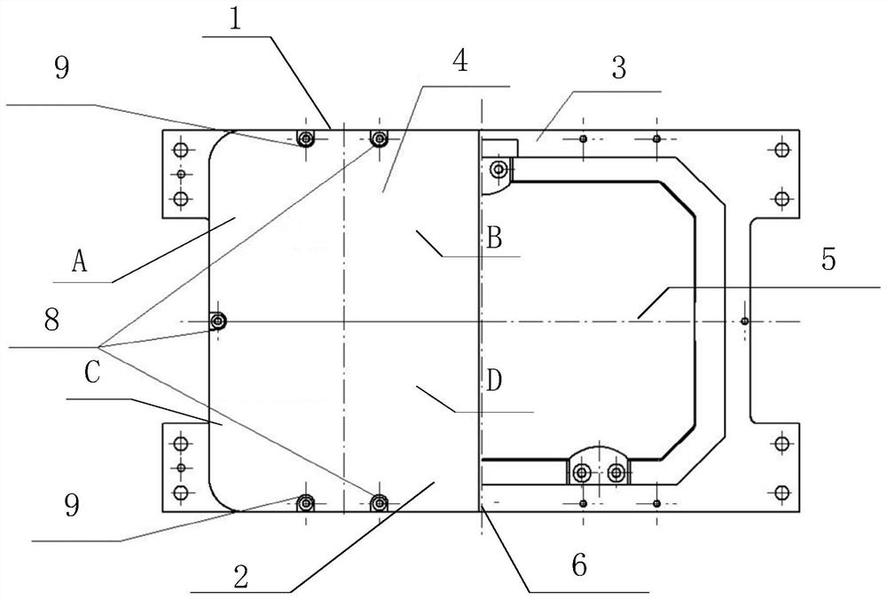
[0004] The object of the present invention is to provide a thermal control device for a space optical mirror, which aims to solve the problems in the prior art that the temperature control accuracy of the thermal control device is insufficient and the heating range is small, which leads to local deformation of the mirror and reduces the shooting accuracy.

Method used


Image

  • A temperature control cover for a space optical mirror
  • A temperature control cover for a space optical mirror
  • A temperature control cover for a space optical mirror

Examples


Embodiment Construction

[0019] In order to make the object, technical solution and advantages of the present invention more clear, the present invention will be further described in detail below in conjunction with the accompanying drawings and embodiments. It should be understood that the specific embodiments described here are only used to explain the present invention, not to limit the present invention.

[0020] It should be noted that when an element is referred to as being “fixed on” or “disposed on” another element, it may be directly on the other element or there may be an intervening element at the same time. When an element is referred to as being "connected to" another element, it can be directly connected to the other element or intervening elements may also be present.

[0021] In addition, it should be noted that the orientation terms such as left, right, up, and down in the embodiments of the present invention are only relative concepts or refer to the normal use state of the product, ...


PUM


Abstract

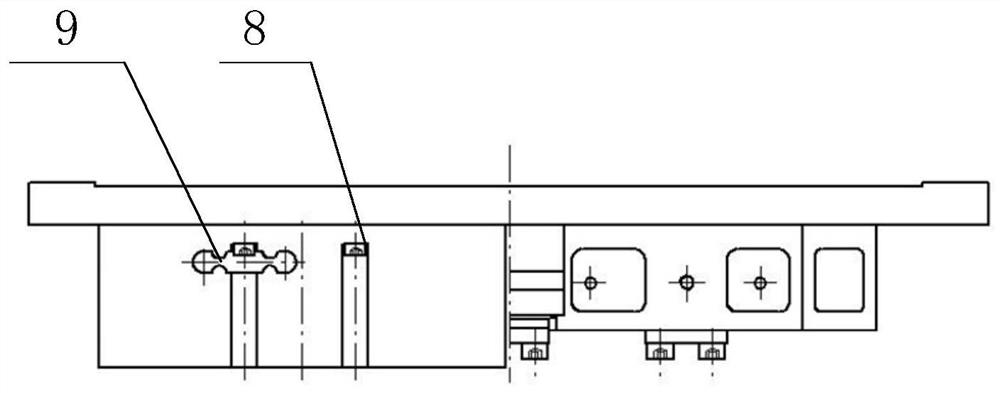
The invention relates to the technical field of thermal control of space optical remote sensors, and discloses a temperature control cover for a space optical reflector. In the inner cavity of the temperature control cover, a plurality of evenly distributed heating zones are arranged on the outside of the temperature control cover, and heating components are arranged on the heating zones, and the heating components are used to heat the temperature control cover. On the one hand, the device ensures the effective release of heat and improves the thermal control efficiency; on the other hand, it ensures that the distance from the heating plate to any position of the temperature control cover is equal, so that the overall heat transfer rate of the temperature control cover is consistent, and the deformation of the temperature control cover caused by temperature changes is reduced. ; By setting expansion joints, the deformation of the center of the temperature control cover is reduced when the temperature rises, so as to adapt to the large deformation caused by the rapid temperature change in space.

Description

technical field [0001] The invention relates to the technical field of thermal control of space optical remote sensors, in particular to a temperature control cover of a space optical mirror. Background technique [0002] Reflector is the most critical optical component in the optical system of space remote sensing camera, and its surface shape accuracy has a direct impact on imaging quality. In a space without gravity environment, the change of temperature is the most direct factor for the change of the surface shape of the reflector. When the visible light camera is in normal imaging, the surface shape accuracy of the reflector is generally better than 12nm (rms value). Any small temperature change will affect the reflector. Mirror shape accuracy is affected. In order to ensure the surface shape accuracy of the reflector, it is necessary to take thermal control measures for the reflector to ensure its temperature stability. When the space camera works in space, it will e...

Claims


Application Information

Patent Timeline
Patent Type & Authority Patents(China)
IPC IPC(8): G02B7/18G02B7/182G05D23/20
CPCG02B7/181G02B7/182G05D23/20
Inventor 刘强何欣崔永鹏张凯袁涛
Owner CHANGCHUN INST OF OPTICS FINE MECHANICS & PHYSICS CHINESE ACAD OF SCI
Learn More