Luneberg lens antenna with movable feed source

A technology of Lunbo lens antenna and Lunbo lens, which is applied to antennas, electrical components, radiation unit covers, etc., can solve the problems of heavy installation and maintenance workload, and achieve the effect of low cost and simple product structure

Pending Publication Date: 2019-10-25
FOSHAN CITY EAHISON COMM
View PDF1 Cites 9 Cited by
  • Summary
  • Abstract
  • Description
  • Claims
  • Application Information

AI Technical Summary

Problems solved by technology

[0003] However, the feed source of most Lunberg lens antennas on the market is fixed to the center of the Lunberg lens. When adjusting the coverage target, it is often necessary to readjust the installation position of the Lunberg lens, which is a heavy workload for installation and maintenance. Work
Although some of the existing Lunberg lens antennas can also realize the function that the feed source can be moved under control, such as the patent application

Method used


Image

  • Luneberg lens antenna with movable feed source
  • Luneberg lens antenna with movable feed source
  • Luneberg lens antenna with movable feed source

Examples


Embodiment 1

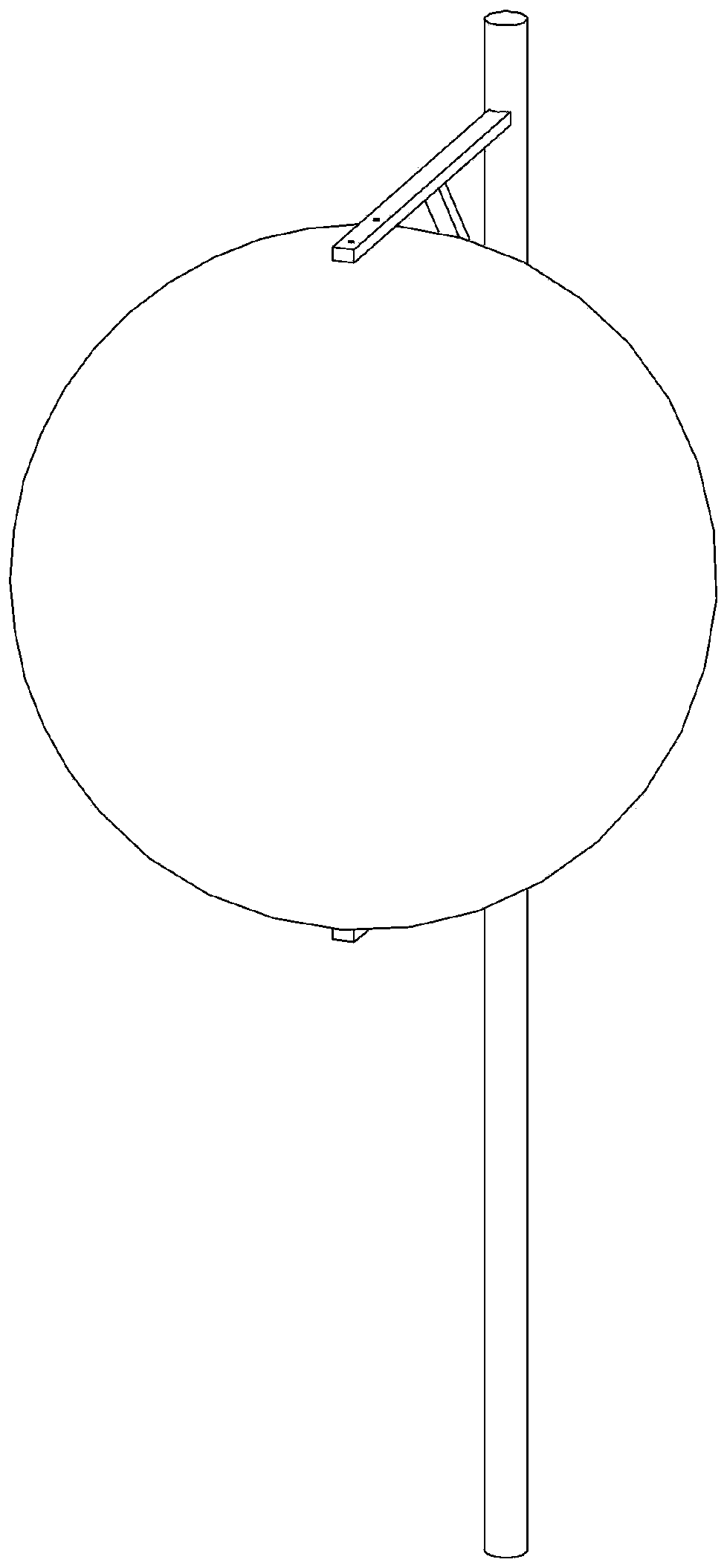
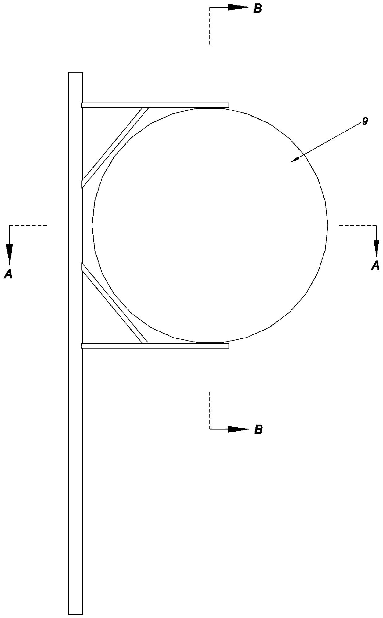
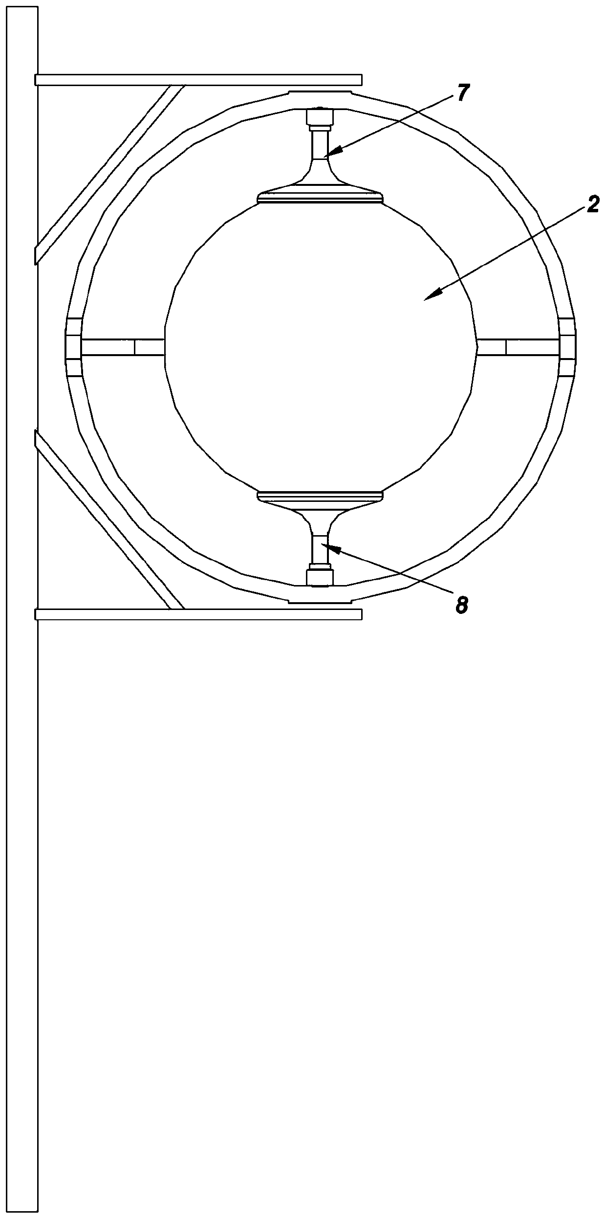
[0036] Such as Figure 1 to Figure 6 As shown, the Luneburg lens antenna with a movable feed source in this embodiment includes: a feed source 1, a Luneburg lens 2, a first track piece 3, a second track piece 4, a connecting ring piece 5, a moving seat 6, an upper Support 7 , lower support 8 and outer cover 9 . in:

[0037] The feed source 1 is a single radiation unit, which includes a reflector 11 and a radiation oscillator 12 .

[0038] Lunberg lens 2 is a global Lunberg lens.

[0039] Such as Figure 5 , Figure 7 , Figure 9 As shown, the first track member 3 is a tooth condition bent into a semicircle, and its teeth point away from the center of the Lunberg lens 2 . The radius of the circle of the first track member 3 is R1, and the center of the circle corresponding to the radius R1 of the first track member 3 is C1. Two ends of the first rail member 3 are directly connected with the connecting ring member 5 to form a hole shaft connection so as to realize the rel...

Embodiment 2

[0051] Such as Figure 11 As shown, the difference between this embodiment and Embodiment 1 is that the feed source is an array composed of four radiating elements (the housing and Lunberg lens are not shown).


PUM


Abstract

The invention provides a Luneberg lens antenna with a movable feed source, and the antenna is simple, compact and stable in structure. The antenna comprises the feed source, a global luneberg lens, afirst track part, a second track part and a connecting ring part. The first rail part is a tooth part bent into a semicircle; the second rail part is also a tooth part bent into a semicircle; the moving seat is provided with a first gear used for being matched with the teeth of the first rail part and a second gear used for being matched with the teeth of the second rail part; the first gear is driven by a first electric part, and the second gear is driven by a second electric device; a first shifting block part used for driving the first rail part to rotate relative to the connecting ring part and a second shifting block part used for driving the second rail part to rotate relative to the connecting ring part are further arranged on the moving seat; and the feed source is fixedly arrangedon the moving seat. A double-track mechanism is adopted, so that the coverage area of multi-beam waves passing through the surface of the luneberg lens can be flexibly adjusted, and the stability andreliability are achieved.

Description

technical field [0001] The invention relates to the technical field of antennas, in particular to a Lunberg lens antenna with a movable feed source. Background technique [0002] The Lunberg lens antenna is a spherical layered dielectric lens antenna. Compared with the parabolic antenna, its main feature is that it can focus the incident wave to a point on the spherical surface, and the multi-beam gain is consistent. At the same time, its own spherical symmetry and Good dielectric performance makes it have the advantages of multi-beam, wide frequency band, and wide scanning angle range. [0003] However, the feed source of most Lunberg lens antennas on the market is fixed to the center of the Lunberg lens. When adjusting the coverage target, it is often necessary to readjust the installation position of the Lunberg lens, which is a heavy workload for installation and maintenance. Work. Although some of the existing Lunberg lens antennas can also realize the function that t...

Claims


Application Information

Patent Timeline
IPC IPC(8): H01Q19/06H01Q15/02H01Q3/02H01Q1/42
CPCH01Q1/42H01Q3/02H01Q15/02H01Q19/06
Inventor 郑洪振李伟芦永超
Owner FOSHAN CITY EAHISON COMM
Why Eureka
Try Eureka