
Vehicle charging control circuit and method thereof

A charging control method and technology for controlling circuits, which are applied in battery circuit devices, secondary battery charging/discharging, circuits, etc., can solve problems such as insufficient voltage, inability to meet users' fast charging, and low output power.

Pending Publication Date: 2019-10-25
珠海英集芯半导体有限公司
View PDF0 Cites 4 Cited by
  • Summary
  • Abstract
  • Description
  • Claims
  • Application Information

AI Technical Summary

Problems solved by technology

The disadvantage of this circuit is that the output power is small, which cannot meet the needs of users for fast charging
[0005] Therefore, the existing car charger technology generally has disadvantages: non-fast charging car chargers have low output power and cannot meet the needs of users for fast charging; USB PD fast charging car chargers have problems due to the drop in output voltage of the cigarette lighter When fast charging is output, the voltage is insufficient, and there are problems such as device charging compatibility

Method used


Image

  • Vehicle charging control circuit and method thereof
  • Vehicle charging control circuit and method thereof
  • Vehicle charging control circuit and method thereof

Examples


Embodiment Construction

[0027] In order to make the object, technical solution and advantages of the invention clearer, the present invention will be further described in detail below in conjunction with the accompanying drawings and embodiments. It should be understood that the specific embodiments described here are only used to explain the present invention, and are not limited to the present invention.

[0028] Embodiment of the on-board charging control circuit:

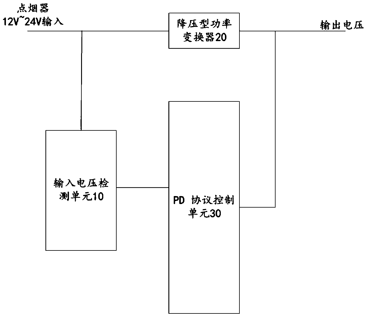
[0029] see image 3, the vehicle charging control circuit of the present invention comprises a vehicle charger, a charging control circuit electrically connected to the vehicle charger, a voltage output terminal electrically connected to the charging control circuit, the charging control circuit comprising an input voltage detection unit 10, a step-down power conversion device 20, PD protocol control unit 30, the input voltage detection unit 10 detects the voltage amplitude signal of the input terminal of the vehicle charger, and send...


PUM


Abstract

The invention discloses a vehicle charging control circuit and a method thereof. The circuit includes a vehicle charger, a charging control circuit and a voltage output end, wherein the charging control circuit includes an input voltage detection unit, a step-down power converter and a PD protocol control unit, the input voltage detection unit is used for detecting a voltage amplitude signal at aninput end of the vehicle charger and transmitting the voltage amplitude signal to the PD protocol control unit, and the PD protocol control unit is used for adjusting the output power of the vehiclecharger according to the voltage amplitude signal and acts on the step-down power converter to control an output voltage of the step-down power converter. The charging control method is applied to thevehicle charging control circuit. The vehicle charging control circuit is advantaged in that the output voltage specification of the USB PD vehicle charger can be automatically adjusted according tothe input voltage, a problem that the output voltage of the vehicle charger is insufficient due to the voltage drop of a vehicle battery is solved, and charging performance is improved.

Description

【Technical field】 [0001] The present invention relates to the technical field of on-board chargers, in particular to an on-board charging control circuit and a charging control method applied to the circuit. 【Background technique】 [0002] Car chargers are a widely used power source for devices. The input end of the car charger is the car cigarette lighter, and the output voltage range of the cigarette lighter is generally between 12V and 24V. There are two main types of car chargers, the first is a non-fast charging car charger, the output voltage is generally 5V, and the output current is about 2A; the other is a car charger with a USB PD fast charging protocol. The output voltage of the car charger can be as high as 20V. But car chargers generally have two defects. One is that the output voltage of the cigarette lighter will drop with the use of the car battery, and the power part of the car charger mostly uses a BUCK step-down circuit. When the battery voltage drops, t...

Claims


Application Information

Patent Timeline
IPC IPC(8): H02J7/00H01M10/44
CPCH02J7/0036H02J7/007H01M10/441H01M10/4257Y02E60/10
Inventor 汤厚涛戴加良
Owner 珠海英集芯半导体有限公司
Learn More