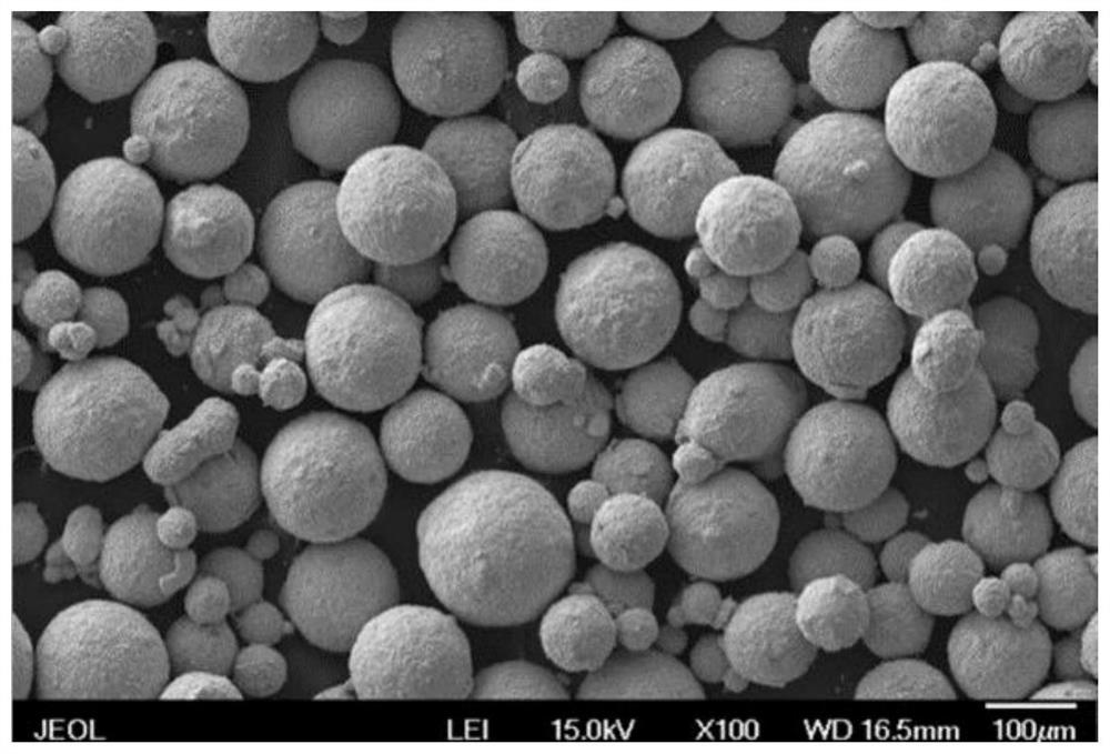
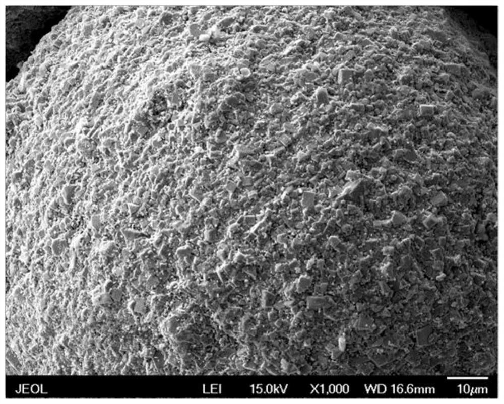
A 3D printed powder material
A technology of 3D printing and mixing powder, applied in the field of 3D printing, can solve problems such as not applicable to the field of 3D printing, and achieve the effect of improving drilling effect and efficiency, and good bending strength
- Summary
- Abstract
- Description
- Claims
- Application Information
AI Technical Summary
Problems solved by technology
Method used
Image
Examples
Embodiment 1
[0103] The components based on the technical solution of the present invention are as follows:
[0104] Sintered WC-Co cemented carbide spherical particles accounted for 10%, coarse crystal or single crystal tungsten carbide particles accounted for 20%, Co-based alloy accounted for 70%;
[0105] Sintered WC-Co cemented carbide spherical particles are: Ct 5.6% ~ 6.0%, Cf ≤ 0.08%, O ≤ 0.1%, Fe ≤ 0.08%, Co 5.8% ~ 6.2%, Cr ≤ 0.05%, Ni ≤ 0.05%, Ti≤0.05%, Si≤0.01%, Ca≤0.01%, the rest is W;
[0106] Coarse crystal or single crystal tungsten carbide particles are: Ct 6.12%, Cf≤0.08%, Cr≤0.03%, Co≤0.02%, Fe≤0.03%, Mo≤0.005%, Ca≤0.002%, Si≤0.003%, Al ≤0.001%, S≤0.005%, O≤0.05%, the rest is W;
[0107] Co-based alloys are: C 1.15%, Mn≤1.0%, W4.0%, Ni≤3.0%, Cr29.0%, Mo≤1.0%, Fe≤3.0%, Si≤2.0%, and the rest is Co.
Embodiment 2
[0109] The components based on the technical solution of the present invention are as follows:
[0110] Sintered WC-Co cemented carbide spherical particles accounted for 10%, coarse crystal or single crystal tungsten carbide particles accounted for 20%, Co-based alloy accounted for 70%;
[0111] Sintered WC-Co cemented carbide spherical particles are: Ct 5.5% ~ 5.8%, Cf ≤ 0.08%, O ≤ 0.1%, Fe ≤ 0.08%, Co 7.5% ~ 8.5%, Cr ≤ 0.05%, Ni ≤ 0.05%, Ti≤0.05%, Si≤0.01%, Ca≤0.01%, the rest is W;
[0112] Coarse crystal or single crystal tungsten carbide particles are: Ct 6.18%, Cf≤0.08%, Cr≤0.03%, Co≤0.02%, Fe≤0.03%, Mo≤0.005%, Ca≤0.002%, Si≤0.003%, Al ≤0.001%, S≤0.005%, O≤0.05%, the rest is W;
[0113] Co-based alloys are: C1.2%, Mn≤1.0%, W4.5%, Ni≤3.0%, Cr29.0%, Mo≤1.0%, Fe≤3.0%, Si≤2.0%, and the rest is Co.
Embodiment 3
[0115] The components based on the technical solution of the present invention are as follows:
[0116] Sintered WC-Co cemented carbide spherical particles accounted for 15%, coarse crystal or single crystal tungsten carbide particles accounted for 40%, Co-based alloy accounted for 45%;
[0117] Sintered WC-Co cemented carbide spherical particles are: Ct 5.6% ~ 6.0%, Cf ≤ 0.08%, O ≤ 0.1%, Fe ≤ 0.08%, Co 5.8% ~ 6.2%, Cr ≤ 0.05%, Ni ≤ 0.05%, Ti≤0.05%, Si≤0.01%, Ca≤0.01%, the rest is W;
[0118] Coarse crystal or single crystal tungsten carbide particles are: Ct 6.12%, Cf≤0.08%, Cr≤0.03%, Co≤0.02%, Fe≤0.03%, Mo≤0.005%, Ca≤0.002%, Si≤0.003%, Al ≤0.001%, S≤0.005%, O≤0.05%, the rest is W;
[0119] Co-based alloys are: C 1.15%, Mn≤1.0%, W4.0%, Ni≤3.0%, Cr29.0%, Mo≤1.0%, Fe≤3.0%, Si≤2.0%, and the rest is Co.
PUM
| Property | Measurement | Unit |
|---|---|---|
| crystal size | aaaaa | aaaaa |
| particle size | aaaaa | aaaaa |
| particle size | aaaaa | aaaaa |
Abstract
Description
Claims
Application Information
 - R&D
- Intellectual Property
- Life Sciences
- Materials
- Tech Scout
- Unparalleled Data Quality
- Higher Quality Content
- 60% Fewer Hallucinations
Browse by: Latest US Patents, China's latest patents, Technical Efficacy Thesaurus, Application Domain, Technology Topic, Popular Technical Reports.
© 2025 PatSnap. All rights reserved.Legal|Privacy policy|Modern Slavery Act Transparency Statement|Sitemap|About US| Contact US: help@patsnap.com


