Physical sample cold-state processing equipment

A kind of processing equipment and cold state technology, which is applied in the field of physical sample cold state processing equipment, can solve the problems of filter blockage, unfavorable drainage, water flow reduction, etc., so as to avoid mesh blockage, facilitate drainage and recycling utilization, The effect of keeping the water body clean

Active Publication Date: 2019-10-29
JIANGSU DAIMIPU PRECISION EQUIP CO LTD
View PDF5 Cites 3 Cited by
  • Summary
  • Abstract
  • Description
  • Claims
  • Application Information

AI Technical Summary

Problems solved by technology

[0002] Water cutting equipment is often used for cold processing of physical patterns. Water cutting is also called water jet, that is, high-pressure water jet cutting technology. It is a machine that uses high-pressure water jet cutting. The current water cutting equipment will be filled with The water body, the high-pressure water flow from the cutting head penetrates the workpiece and will be injected into the water body, thereby filling the chips into the water body. However, a large amount of emery and chips are often left on the surface of the workpiece due to sputtering, which is easy to be damaged when the cutting head moves and cuts. The high-pressure water flow is blocked, causing the cutting edge to be uneven, and the water in the chassis will gradually increase as the cutting progresses, and the water body needs to be drained. Currently, a filter is installed at the drain pipe to filter the emery and chips when draining. However, The filter screen is in a fixed state. The accumulation of corundum and cuttings on the filter screen will cause the filter screen to be blocked, thereby reducing the flow of the water body, which is not conducive to drainage. Therefore, we propose a cold processing equipment for physical samples to solve the above problems. question

Method used


Image

  • Physical sample cold-state processing equipment
  • Physical sample cold-state processing equipment
  • Physical sample cold-state processing equipment

Examples


Embodiment Construction

[0018] The following will clearly and completely describe the technical solutions in the embodiments of the present invention with reference to the accompanying drawings in the embodiments of the present invention. Obviously, the described embodiments are only some, not all, embodiments of the present invention. Based on the embodiments of the present invention, all other embodiments obtained by persons of ordinary skill in the art without making creative efforts belong to the protection scope of the present invention.

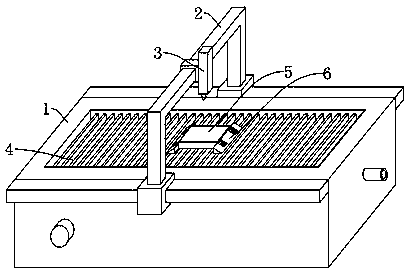
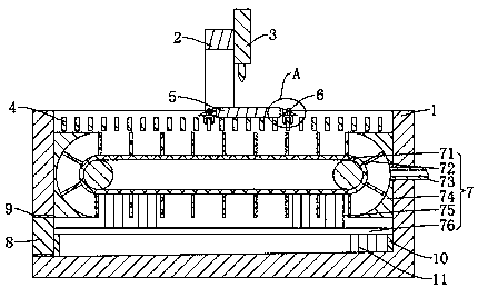
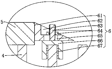
[0019] see Figure 1-5 , the present invention provides a technical solution: a cold-state processing equipment for physical samples, including a chassis 1, guide rails are installed on the two side walls of the chassis 1, and the gantry 2 is slidingly clamped on the guide rails, and the water cutting machine is installed on the gantry 2 The head 3 and the top of the inner wall on both sides of the chassis 1 are fixedly installed with a plurality of storage bo...


PUM


Abstract

The invention discloses physical sample cold-state processing equipment which comprises a case, a guide rail is mounted on the two side walls of the case; a portal frame is in sliding fit with the guide rail in a clamping manner; a water cutting head is mounted on the portal frame; a plurality of placing plates are fixedly mounted between the tops of the inner walls of the two sides of the case; aworkpiece is placed on the placing plate below the water cutting head; flow-guiding clamping plates are mounted on the placing plates on the two sides of the workpiece and tightly press the two sidesof the workpiece; and a dynamic filtering mechanism is mounted between the inner walls of the case below the placing plates. The workpiece is placed on each of the placing plates, clamped and fixed by the flow-guiding clamping plates; the water cutting head cuts the workpiece; the dynamic filtering mechanism pushes the water body in the case to fluctuate the water surface; the water surface fluctuation pushes through the surface of the workpiece along the flow-guiding clamping plates, so that carborundum and cuttings are pushed in the water body in the case; the dynamic filtering mechanism dynamically filters the water body in the case; and during the filtering process, the water bodies at the upper part and the bottoms of the case are divided, and the water body at the drainage part is kept clean, so that drainage and cyclic utilization are facilitated.

Description

technical field [0001] The invention relates to the technical field of cold processing, in particular to a cold processing equipment for physical samples. Background technique [0002] Water cutting equipment is often used for cold processing of physical patterns. Water cutting is also called water jet, that is, high-pressure water jet cutting technology. It is a machine that uses high-pressure water jet cutting. The current water cutting equipment will be filled with The water body, the high-pressure water flow from the cutting head penetrates the workpiece and will be injected into the water body, thereby filling the chips into the water body. However, a large amount of emery and chips are often left on the surface of the workpiece due to sputtering, which is easy to be damaged when the cutting head moves and cuts. The high-pressure water flow is blocked, causing the cutting edge to be uneven, and the water in the chassis will gradually increase as the cutting progresses, ...

Claims


Application Information

Patent Timeline
Patent Type & Authority Applications(China)
IPC IPC(8): B24C1/04B24C3/02B24C9/00B01D33/056B01D33/46
CPCB01D33/056B01D33/46B24C1/045B24C3/02B24C9/00B24C9/006
Inventor 刘佳
Owner JIANGSU DAIMIPU PRECISION EQUIP CO LTD
Why Eureka
Try Eureka