Evaporator of air source heat pump and design method and air source heat pump comprising same

A technology of air source heat pump and design method, which is applied in the direction of evaporator/condenser, lighting and heating equipment, refrigeration and liquefaction, etc. It can solve the problem of fast frosting on the surface of fins, fast blocking of channels by frost layer, and defrosting cycle Short and other problems, to achieve the effect of accelerated frosting speed, long growth and blockage time, and low cost

Pending Publication Date: 2019-10-29
SHANDONG QIWEITE SOLAR TECH CO LTD
View PDF0 Cites 3 Cited by
  • Summary
  • Abstract
  • Description
  • Claims
  • Application Information

AI Technical Summary

Problems solved by technology

[0006] In view of the above defects and deficiencies of the prior art, the present invention provides an air source heat pump evaporator and a design method and an air source heat pump containing the evaporator, which are used to solve the problem of frosting on the fin surface of the air source heat pump evaporator in the prior art The speed is faster, the frost layer blocks the channel faster, and the defrosting cycle is shorter

Method used


Image

  • Evaporator of air source heat pump and design method and air source heat pump comprising same
  • Evaporator of air source heat pump and design method and air source heat pump comprising same
  • Evaporator of air source heat pump and design method and air source heat pump comprising same

Examples


Embodiment 1

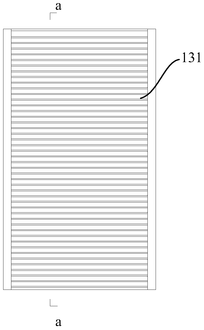
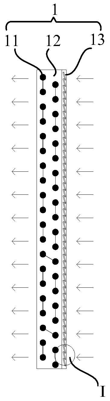
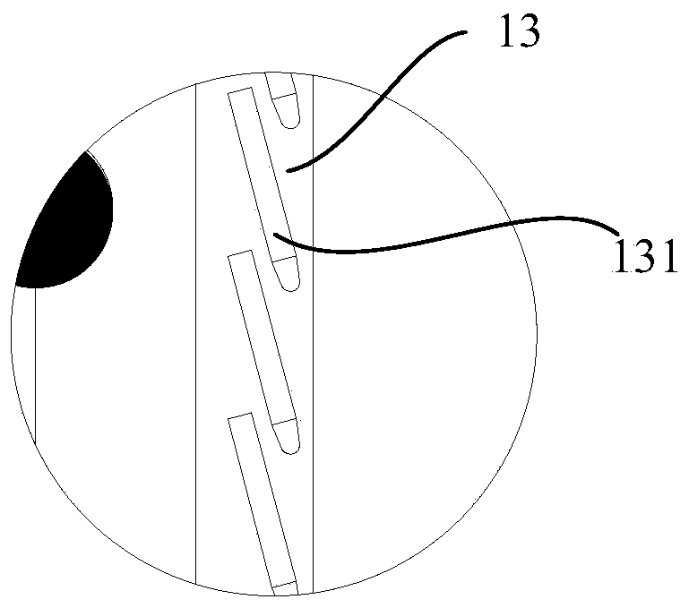
[0075] The invention provides a design method of an air source heat pump evaporator, the air source heat pump evaporator includes a refrigerant pipeline and a plurality of fins mounted in series on the refrigerant pipeline, and a design capable of The guiding structure that guides the water vapor in the air to liquefy instead of desublimate, based on the design method in the present invention, this embodiment provides a Figure 1-4 The shown air source heat pump evaporator 1, the air source heat pump evaporator 1 includes a refrigerant pipeline 11 and a plurality of fins 12 mounted on the refrigerant pipeline 11 in series, and is arranged on the windward side of the air source heat pump evaporator 1 There is a guide structure (grid 13) that can guide the water vapor in the air to liquefy into water rather than condense into frost.

[0076] An air source heat pump evaporator and design method of the present invention and an air source heat pump containing the evaporator are pro...

Embodiment 2

[0083] Such as Figure 5 As shown, this embodiment provides an air source heat pump evaporator, which is different from Embodiment 1 in that the blade head 1311 on the grid blade 131 in this embodiment includes a first slope 13111, a second slope 13114 and a cylindrical surface 13112, the two sides of the cylindrical surface 13112 are respectively tangent to one side of the first slope 13111 and the second slope 13114, and the other side of the first slope 13111 and the second slope 13114 are along the air flow direction It is opened and connected to the two sides of the blade body 1312 in a smooth transition, and a hollow structure 13113 is provided in the blade head 1311. This structure can make the blade head 1311 more smooth and not easy to attach, and in order to achieve better results In this embodiment, the first slope 13111 and the second slope 13114 are arranged symmetrically on both sides of the cylindrical surface 13112, and the angle φ between the first slope 13111...

Embodiment 3

[0086] Such as Figure 6-8 As shown, this embodiment provides an air source heat pump evaporator 1, which differs from Embodiment 1 in that the gap direction of the blades 131a of the grid 13a is the same as the gap direction of the fins 12 of the air source heat pump evaporator 1 The number of blades 131 a of the grid 13 a corresponds to the number of the fins 12 , and the tails of the blades 131 a are in smooth contact with the windward side of the fins 12 .


PUM


Abstract

The invention provides an evaporator of an air source heat pump and a design method and the air source heat pump comprising the same for solving the problems that the frosting speeds of surfaces of fins of the air source heat pump evaporator are relatively high, the speeds of the frosted layers plugging a channel are relatively high and the defrosting period is relatively short in the prior art. The evaporator of the air source heat pump comprises a refrigerant pipeline and a plurality of fins mounted on the refrigerant pipeline in a serial manner. The design method comprises a step of designing a guiding structure capable of guiding water vapor in air to be liquefied rather than condensed on a windward sides of the fins, so that water vapor in the air is frozen rather than frosted, and therefore, purposes that the frosting and defrosting periods are prolonged, the defrosting energy consumption is reduced, and the integral performance of a unit is improved are achieved. The defrostingperiod of the evaporator of the air source heat pump in a same working condition and under a defrosting condition is about three times of an original period, so that the defrosting period is prolongedgreatly, and the work efficiency of the air source heat pump is improved. The evaporator of the air source heat pump is simple and reasonable in structure, low in cost and easy to implement and doesnot affect normal operation of the system.

Description

technical field [0001] The invention relates to the field of defrosting and defrosting, in particular to an air source heat pump evaporator, a design method and an air source heat pump including the evaporator. Background technique [0002] In recent years, with the improvement of people's living standards and the country's emphasis on environmental protection, energy conservation and emission reduction, air source heat pump units have been widely used as energy-saving equipment. The air source heat pump unit is mainly composed of four parts: evaporator, compressor, condenser and throttling device. The heat cycle process transfers the heat absorbed from the external environment to water or air for heating. The biggest problem encountered by air source heat pump units during heating operation in winter is frosting on the surface of evaporator fins. Due to the formation and growth of the frost layer, the heat transfer resistance between the surface of the evaporator fin and ...

Claims


Application Information

Patent Timeline
Patent Type & Authority Applications(China)
IPC IPC(8): F25B39/02F25B47/00
CPCF25B39/02F25B47/00
Inventor 李文李群山
Owner SHANDONG QIWEITE SOLAR TECH CO LTD
Why Eureka
Try Eureka