Current transformer polarity measuring device

A current transformer, polarity measurement technology, applied in the direction of measurement device, measurement of electricity, measurement of electric variables, etc., can solve the problems of difficult connection, randomness of equipment, safety risks of adults and equipment, etc., to reduce human and equipment. Safety risks, quick and easy connection, and considerable economic benefits

Pending Publication Date: 2019-10-29
GUANGDONG POWER GRID CO LTD +1
View PDF0 Cites 0 Cited by
  • Summary
  • Abstract
  • Description
  • Claims
  • Application Information

AI Technical Summary

Problems solved by technology

However, there are many problems in the practical application of this method. First, the equipment used in the test needs to be temporarily raised by the test personnel, including batteries, experimental lines, pointer microammeters, lap rods and other materials. The preparation of materials is time-consuming and laborious; secondly, the construction of the equipment There are arbitrariness, instability and inconvenient operation. For example, the test line is usually fixed with the battery by insulating tape, and the pulling during the test is easy to damage the stability of the connection. At the same time, the connection between the test line and both sides is not easy to operate and the There is a lot of demand for personnel, and there are coordination problems
Especially when measuring outdoor CTs with high voltage levels and high structures, it is difficult to pressurize at one time. It is necessary to climb up the frame with the help of an insulating ladder to pressurize, which poses a greater risk to personal and equipment safety.
Moreover, the operation requires two groups of personnel, one group uses dry batteries to apply impulse voltage on the primary side, and the other group uses pointer microammeters to measure on the secondary side. The deflection direction can be used to determine the polarity of the CT. Obviously, such a measurement method consumes a lot of manpower and material resources for the CT polarity measurement.

Method used


Image

  • Current transformer polarity measuring device
  • Current transformer polarity measuring device
  • Current transformer polarity measuring device

Examples


Embodiment 1

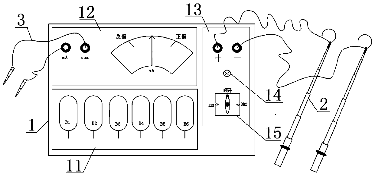
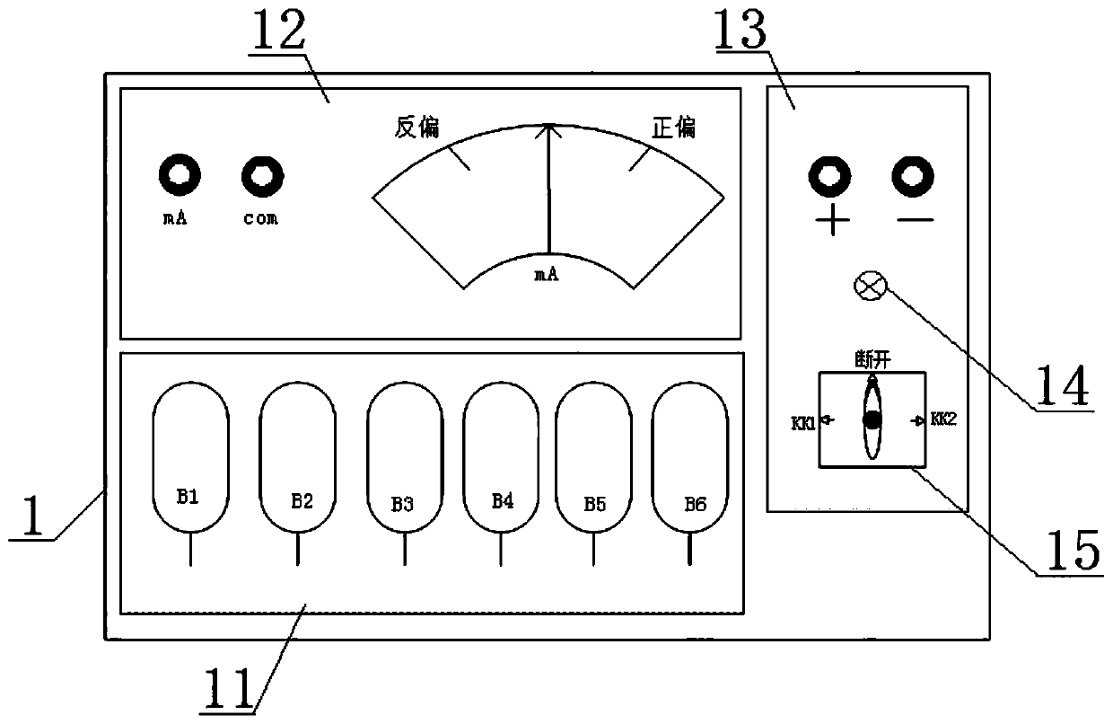
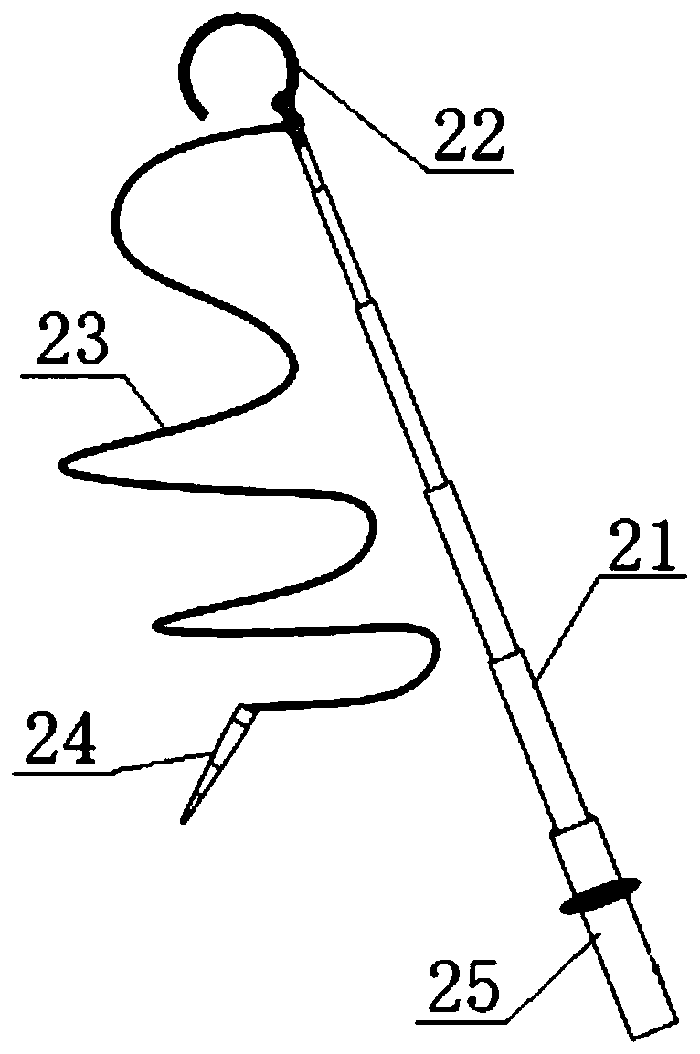
[0034] Such as figure 1 and figure 2 As shown, a current transformer polarity measuring device includes a device body 1 and an external primary test line hook 2 and a secondary test line 3. The device body 1 includes a power supply module 11, a polarity indicating module 12, a primary pressurization control module 13;

[0035] The power supply module 11 is composed of a plurality of rechargeable storage batteries connected in series, the power supply module 11 is electrically connected to the primary pressurization control module 13, the primary pressurization control module 13 is connected to the primary test line hook 2, and the other end of the primary test line hook 2 is connected to the current The primary side of the transformer is connected, the primary pressurization control module 13 controls the voltage output of the power supply module 11, and pressurizes the current transformer once through the primary test line hook 2;

[0036] The polarity indication module 12...


PUM


Abstract

The invention relates to the field of polarity measurement of current transforms, and especially relates to a current transformer polarity measuring device. The current transformer polarity measuringdevice comprises a device body and an external primary test line hook and a secondary test line; the device body comprises a power module, a polarity indicating module and a primary pressurization control module; the power module is electrically connected with the primary pressurization control module; the primary pressurization control module is connected with a primary side of a current transformer through the primary test line hook; the primary pressurization control module controls the voltage output of the power module, and performs primary pressurization on the current transformer; and the polarity indicating module is connected with a secondary side of the current transformer through the secondary test line, and the polarity indicating module is used for current measurement and indicating the polarity. According to the current transformer polarity measuring device provided by the invention, the primary pressurization mode is improved, the primary pressurization can be carried out without climbing, and a polarity measurement operation of the current transformer can be completed only by one person, which is convenient and rapid; and besides, the safety risk is reduced, manpower and material resources are saved, and considerable economic benefits are achieved.

Description

technical field [0001] The invention relates to the field of polarity measurement of current transformers, in particular to a polarity measurement device for current transformers. Background technique [0002] The current transformer includes the primary side incoming line terminal P1, the primary side outgoing line terminal P2, the secondary side head end S1 and the secondary side tail end S2. These four ports should be connected to the corresponding lines respectively. However, S1 and S1 may appear during wiring. If the polarity of the S2 line is reversed, the direction of the measured current will be reversed, causing protection malfunctions and instrument damage. Therefore, a polarity test is required to protect the correctness of the polarity of the current transformer. [0003] At present, there are three main methods used in current transformer (CT) polarity testing, which are DC method, AC method and instrument method. Among them, the "DC method" is widely used for t...

Claims


Application Information

Patent Timeline
Patent Type & Authority Applications(China)
IPC IPC(8): G01R31/06
CPCG01R31/72
Inventor 欧韦宜徐庆焯黄佳允陈忠颖甘锴梁永成苏思韵龙海超吴昊石慧梁志澎湃李培坚张慧华覃汉华李瑞强陈百盛
Owner GUANGDONG POWER GRID CO LTD
Why Eureka
Try Eureka