

Method and system for assessing laryngeal and vagus nerve integrity in patients under general anesthesia
A technique of recurrent laryngeal nerve and vagus nerve, which is applied in the field of evaluating the integrity and system of the recurrent laryngeal nerve and vagus nerve in patients under general anesthesia, and can solve problems such as easy movement of electrodes.
- Summary
- Abstract
- Description
- Claims
- Application Information
AI Technical Summary
Problems solved by technology
Method used
Image

Examples
example 1
[0071] Example 1 - Patient Study
[0072] A study was conducted on 15 patients who underwent neck surgery. Table 1 (shown below) shows the demographics, diagnosis, and type of surgery for each patient. The anesthesia protocol consisted of total intravenous anesthesia (TIVA) with propofol and remifentanil at standard weight-based doses.
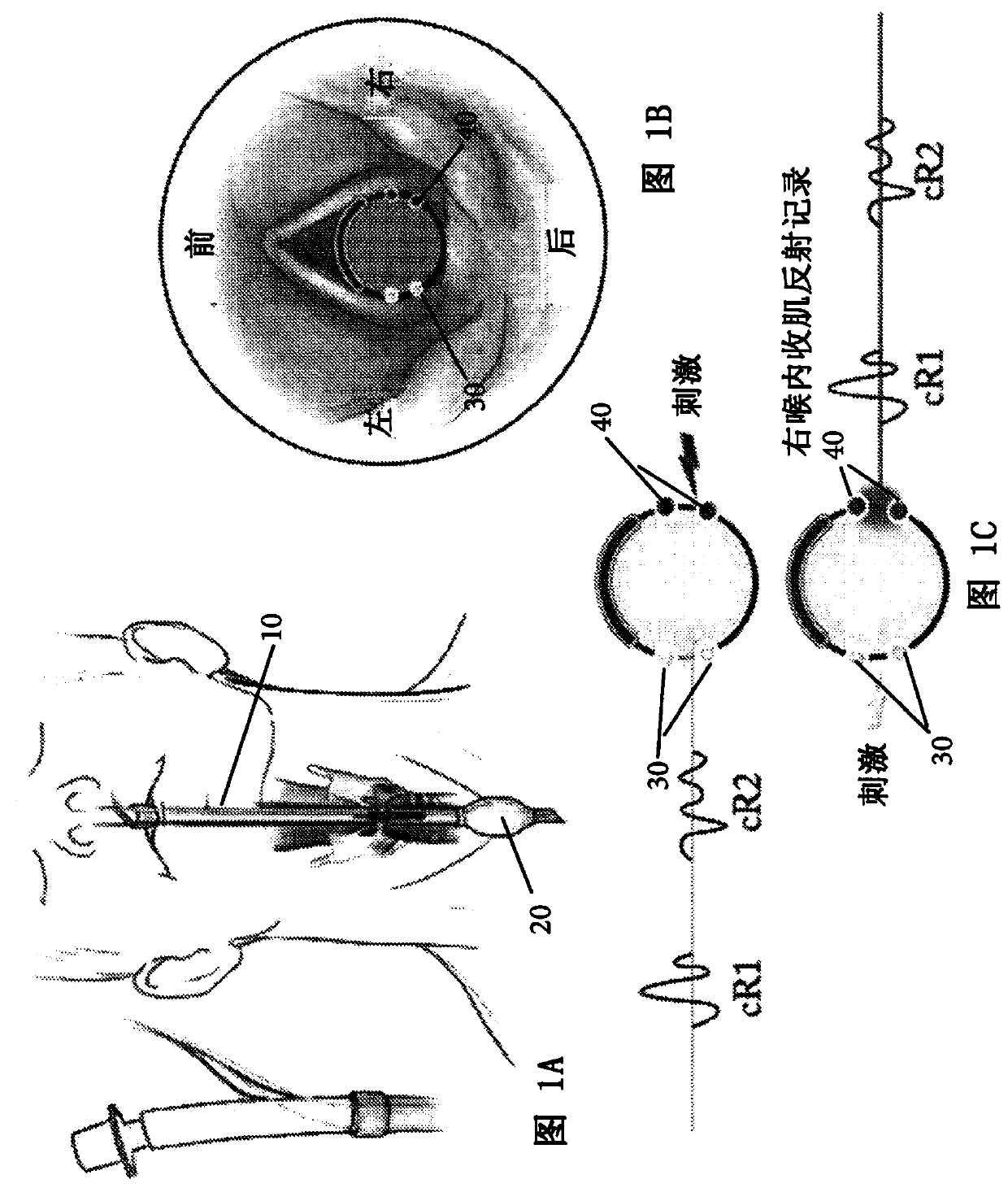
[0073] After induction of general anesthesia, the patient was inserted with a TriVantage Endotracheal Tube (NIMTriVantage TM , Medtronics Xomed; Jacksonville, FL, USA) containing conductive silver ink surface electrodes embedded on both sides (see Figures 1A-1C ). These electrodes are in direct contact with the right and left vocal cords ( Figure 1A and 1B ). will recognize that Figure 1A and 1B The shown cannula structure and electrode structure and arrangement are the same as Figure 2-6 The example shown in is different. More specifically, Figure 1A and 1B Depicted is a cannula 10 having a first inflatable member (balloon ...
example 2
[0114] Example 2 - Patient Study
[0115] program
[0116] A total of 10 patients were enrolled. All patients were monitored with an endotracheal tube (NIM Trivantage catheter, Medtronic). Perform direct laryngoscopy with suspension of the larynx. Different laryngeal subsites are stimulated using bipolar probes. Bipolar stimulation is used to minimize current spreading from the point of stimulation. Subsites include the anterior and posterior membranous vocal cords, the posterior supraglottis on the medial surface of the arytenoid cartilage, the middle false vocal cords, the petiole of the epiglottis, the tip of the epiglottis, and the subglottis. The IRB-approved maximum current was 10 mA, all subsites were stimulated within this level, and vocal cord responses were recorded by visual and endotracheal tube electrodes. Under 10 mA stimulation, subsites that evoked bilateral reflex responses were stimulated starting at 3 mA and increasing in 1 mA increments to determin...
example 3
[0122] Figure 15 is a cross-sectional view of an exemplary electrode portion of a cannula according to the present invention. Figure 15 Example dimensions and example locations for different types of electrodes that are part of the cannula are listed. In this example, each recording electrode has a width of about 3 mm and a length of about 30 mm. As shown, the inter-electrode gap between adjacent recording electrodes was approximately 7 mm on each side of the cannula. Each stimulating electrode has a width of about 2 mm and a length of about 50 mm. As shown, the inter-electrode gap between adjacent recording electrodes was approximately 4 mm. will understand, Figure 15 The recording electrodes in can correspond to Figure 13 In the recording electrodes 530, 540, the stimulating electrodes can correspond to Figure 13 The stimulating electrode 550 in.
[0123] Figure 10 , 11 and 14 show vocal cord level markers (cross symbols) that aid in positioning of the device ...
PUM
 Abstract
Description
Claims
Application Information