Elbow joint prosthesis

An elbow joint and prosthesis technology, applied in the field of medical prostheses, can solve the problems of humeral prosthesis shaking, articular surface wear, humeral prosthesis or ulnar prosthesis loosening, etc., to improve accuracy, ensure stability, and improve stability. sexual effect

Pending Publication Date: 2019-11-01
BEIJING CHUNLIZHENGDA MEDICAL INSTR
View PDF0 Cites 5 Cited by
  • Summary
  • Abstract
  • Description
  • Claims
  • Application Information

AI Technical Summary

Problems solved by technology

[0003] However, when the elbow joint prosthesis is in use, there are the following deficiencies: on the one hand, since the elbow joint prosthesis is connected to the humeral prosthesis and the ulnar prosthesis through the joint shaft, it needs to first place the ulnar prosthesis in use. After the connection with the humeral prosthesis is completed outside the human body, the ulnar prosthesis and humeral prosthesis are fixed in the corresponding medullary cavity as a whole, which can easily cause inaccurate fixed positions of the ulnar prosthesis and humeral prosthesis in the medullary cavity , resulting in surgical failure or the need to re-fix the position of the prosthesis in the medullary cavity, thereby increasing the difficulty of the doctor's operation during the operation; gap, so that the ulnar prosthesis can rotate relative to the humeral prosthesis, and at the same time, the swing of the ulnar prosthesis relative to the humeral prosthesis can be realized through this gap, so as to avoid the shearing caused by the rotation and swing of the radius bone of the human body Stress is transmitted to the elbow joint prosthesis, bone cement or bone interface to cause loosening or dislocation of the elbow joint prosthesis, but this also causes a large gap between the ulnar prosthesis and the humeral prosthesis to a certain extent. Shaking problem, thus easily causing the loosening of the humeral prosthesis or ulnar prosthesis, reducing the connection stability of the elbow prosthesis, and even when the gap is large, it is easy to cause the wear of the articular surface at the elbow joint of the human body

Method used


Image

  • Elbow joint prosthesis
  • Elbow joint prosthesis
  • Elbow joint prosthesis

Examples


Embodiment Construction

[0029] Embodiments of the technical solutions of the present invention will be described in detail below in conjunction with the accompanying drawings. The following examples are only used to illustrate the technical solutions of the present invention more clearly, and therefore are only examples, rather than limiting the protection scope of the present invention.

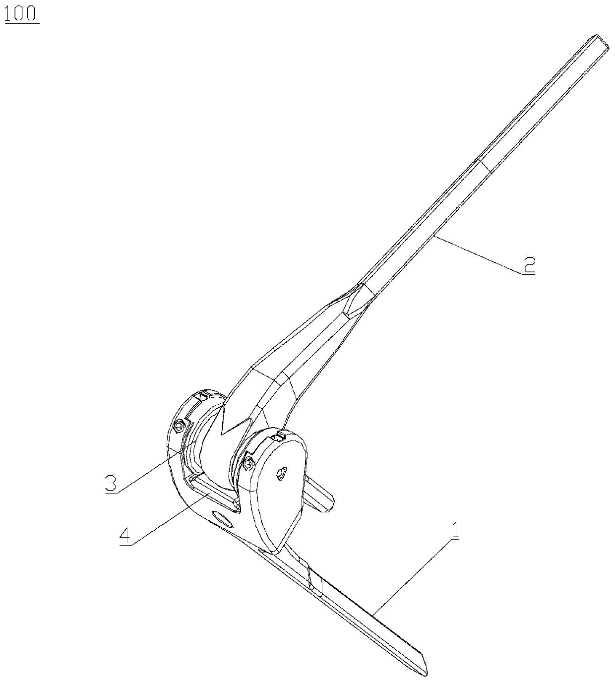
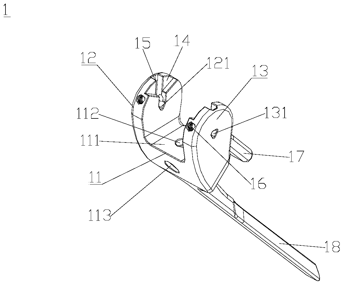
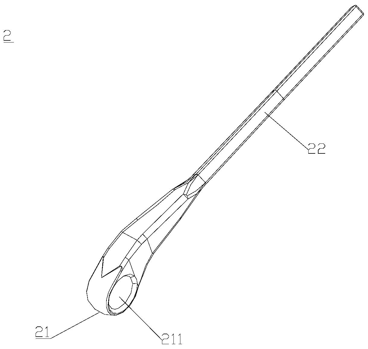
[0030] figure 1 The structure of the elbow joint prosthesis 100 according to the present invention is shown. to combine Figure 1 to Figure 4 As shown, the elbow joint prosthesis 100 includes: a humeral prosthesis 1, first lugs 12 extending away from the length direction of the humeral prosthesis 1 are respectively formed on opposite sides of the connecting end 11 of the humeral prosthesis 1 And the second lug 13, the first lug 12 is provided with the first through hole 121, the second lug 13 is provided with the second through hole 131 coaxial with the first through hole 121; The end 21 of the prosthesis 2 oppo...


PUM


Abstract

The invention relates to the technical field of medical prostheses and discloses an elbow joint prosthesis. The elbow joint prosthesis comprises a humerus prosthesis, a ulna prosthesis and a rotatingshaft assembly, wherein a first lug and a second lug extending out away from the length direction of the humerus prosthesis are formed on two opposite sides of a connecting end of the humerus prosthesis respectively, a first through hole is formed in the first lug, and a second through hole coaxial with the first through hole is formed in the second lug; a third through hole is formed in one end,opposite to the connecting end, of the ulna prosthesis; the rotating shaft assembly comprises a rotating shaft for penetrating through the first through hole, the second through hole and the third through hole simultaneously to rotationally connect the humerus prosthesis and the ulna prosthesis. The rotating shaft is set to telescope in the axial direction of the rotating shaft, so that after a first end of the rotating shaft is placed in the first through hole in an initial state, a second end of the rotating shaft can be placed in the second through hole in a compressed state. The elbow joint prosthesis can improve accuracy of fixed connection with a medullary cavity to ensure stability after connection.

Description

technical field [0001] The invention relates to the technical field of medical prosthesis, in particular to an elbow joint prosthesis. Background technique [0002] Elbow joint prosthesis is a surgical implant used in elbow joint replacement to replace the elbow joint of human patients. It is mainly composed of humeral prosthesis, ulnar prosthesis and joint shaft. The humeral prosthesis is used to connect with the humerus of the human body, the ulnar prosthesis is used to be connected with the ulna of the human body, and the joint shaft is used to connect the ends of the humeral prosthesis and the ulnar prosthesis so that the two can rotate relatively. [0003] However, when the elbow joint prosthesis is in use, there are the following deficiencies: on the one hand, since the elbow joint prosthesis is connected to the humeral prosthesis and the ulnar prosthesis through the joint shaft, it needs to first place the ulnar prosthesis in use. After the connection with the humera...

Claims


Application Information

Patent Timeline
Patent Type & Authority Applications(China)
IPC IPC(8): A61F2/38
CPCA61F2/3804A61F2002/3822A61F2002/3831
Inventor 付中国王文龙史春宝郭靖解凤宝
Owner BEIJING CHUNLIZHENGDA MEDICAL INSTR
Why Eureka
Try Eureka