Rod-holding and backward walking machine with sliding base as well as mounting and use methods of rod-holding and backward walking machine

A technology of sliding base and backward walking is applied in sports accessories, training equipment for adjusting cardiovascular system, training equipment for adjusting coordination, etc.

Inactive Publication Date: 2019-11-01
陈科明
View PDF9 Cites 7 Cited by
  • Summary
  • Abstract
  • Description
  • Claims
  • Application Information

AI Technical Summary

Problems solved by technology

[0008] In the prior art, the backward walking method with a pole (stick) is complex in structure, unsightly and wastes space, and the fitness method is single

Method used


Image

  • Rod-holding and backward walking machine with sliding base as well as mounting and use methods of rod-holding and backward walking machine
  • Rod-holding and backward walking machine with sliding base as well as mounting and use methods of rod-holding and backward walking machine
  • Rod-holding and backward walking machine with sliding base as well as mounting and use methods of rod-holding and backward walking machine

Examples


Embodiment 1

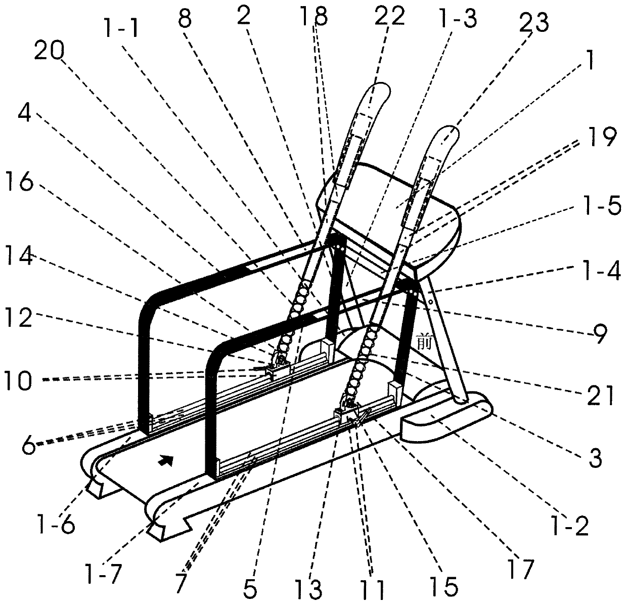
[0275] Embodiment 1: as Figure 1-9As shown, the sliding base holding a rod and the installation and use method thereof include: an electric treadmill (1), a left base frame (1-1), a right base frame (1-2), a left column (1-3 ), the right column (1-4), the fixed connecting rod (1-5), the left frame of the running bench (1-6), the right frame of the running bench (1-7), the front frame of the left limit groove frame (2 ), the front frame of the right limit channel frame (3), the rear frame of the left limit channel frame (4), the rear frame of the right limit channel frame (5), the left linear guide rail (6), the right linear guide rail (7), the left Limiting groove of motion rod (8), limiting groove of right motion rod (9), left sliding block with lock (10), right sliding block with locking (11), bearing with seat on left (12), bearing with seat on right ( 13), left bearing shaft (14), right bearing shaft (15), left exercise rod support (16), right exercise rod support (17), ...

Embodiment 2

[0318] Embodiment 2: as Figure 10-11 As shown, the left belt lock slider (10) includes a left belt lock slider (10) body, and a slider screw hole (101) that is opened on one of the left and right sides of the body and vertically passes through the side body. ), and the slider tightness adjustment device (102),

[0319] The slider tightness adjustment device (102) comprises a bolt part (1021) matched with the thread of the slider screw hole (101) and a handle part (1022) screwed and fixed to the bolt part (1021),

[0320] The bolt part (1021) of the slider tightness adjustment device (102) is screwed in the slider screw hole (101), and when the slider tightness adjustment device (102) is rotated clockwise or counterclockwise, the slider tightness adjustment device (102) ) the top of the bolt part (1021) will gradually contact or leave the left linear guide rail (6), so as to achieve the purpose of gradually increasing the resistance until it is completely locked or gradually ...

Embodiment 3

[0328] Embodiment 3: as Figure 5 , Image 6 , Figures 12 to 17 As shown, the left movement rod limiting groove (8) can adjust the width of the groove body so as to adjust the left sleeve type telescopic movement rod (18) to swing when supporting and lifting with the axis of the left bearing shaft (14) as the fulcrum Movement resistance strength during exercise, its width (resistance) adjustment structure is: comprise: front belt block bearing (801), front bearing shaft (802), front left nut (803), front right nut (804), front synchronous belt Wheel (805), rear belt seat bearing (806), rear bearing shaft (807), rear left nut (808), rear right nut (809), rear timing pulley (810), adjustment knob (811), timing belt (812), left brake frame (813), left brake pad (814), right brake frame (815), right brake pad (816), nut sleeve hole (817), brake pad installation groove (818), shock absorber Pad (819), wherein,

[0329] The model structure of the front bearing unit (801) is the...


PUM


Abstract

The invention provides a rod-holding and backward walking machine with a sliding base as well as mounting and use methods of the rod-holding and backward walking machine, and belongs to the fields ofexercise machines and exercise methods. The rod-holding and backward walking machine comprises an electric backward walking machine body, and is characterized in that left and right limiting groove rack front frames, left and right limiting groove rack rear frames, left and right linear guider rails, left and right moving rod limiting grooves, left and right sliders with locks, left and right bearings with bases, left and right bearing shafts, left and right moving rod brackets, left and right sleeving type telescopic moving rods, left and right compression springs, left and right handles, a locking mechanism, and left and right protection boards are respectively arranged on left and right running platform racks, wherein the width of the moving rod limiting grooves is adjustable, and safety protection devices are arranged. The rod-holding and backward walking machine has the advantages of being simple, attractive, firm and space-saving, and has the dual efficacies of rod-holding exercise and backward walking, the resistance intensity can be adjusted, meanwhile, the upper half body and the lower half body are exercised, various exercise methods are available, exercise can be carriedout when electricity is available or not available, the safety factor of exercise is enhanced, and the movement method, movement pleasure and movement effect are increased.

Description

technical field [0001] A sliding base holding a rod reversing machine and its installation and use methods belong to the field of fitness equipment and fitness methods, and specifically relates to a sliding base holding a rod reversing machine and its installation and use methods. Background technique [0002] Walking with sticks, also known as cross-country walking, originated in Finland and evolved from cross-country skiing. It is one of the fastest growing outdoor aerobic sports in the world. On the basis of ordinary walking, walking with sticks mobilizes the upper limbs to participate in sports through two canes, so as to realize whole-body exercise. Since both hands need to push the walking stick one after another, it will move the upper body, which can strengthen the back and abdominal muscles, legs and arms, and at the same time can promote cardiopulmonary function. Unlike normal walking, which only uses two legs, the body is 70 when walking 90% of the muscles are in...

Claims


Application Information

Patent Timeline
Patent Type & Authority Applications(China)
IPC IPC(8): A63B22/02A63B23/035A63B71/00
CPCA63B22/0235A63B23/03508A63B71/0054A63B2022/0278A63B2230/06
Inventor 陈科明
Owner 陈科明
Why Eureka
Try Eureka