Glasses foot machining shaping mold and machining shaping method

A technology for processing molding and mirror feet, which is applied to home appliances, other household appliances, frames, etc., can solve the problems of increased processing costs of mirror feet, increased materials used for metal poles, and increased difficulty of grinding incisions, etc., to achieve better product quality , The effect of reducing the material used for metal struts and increasing the yield

Pending Publication Date: 2019-11-01
厦门立扬光学科技有限公司
View PDF0 Cites 2 Cited by
  • Summary
  • Abstract
  • Description
  • Claims
  • Application Information

AI Technical Summary

Problems solved by technology

[0005] 1. The ferrule structure greatly increases the material used for the metal pole, which is about 1 / 4 of the original material, and the broken tail section after processing is discarded, resulting in a lot of waste, the processing cost of the temples is greatly increased, and the cost of glasses also increased;
[0006] 2. The tail section of the ferrule needs to be broken to pull it out. The breaking operation is very difficult. After the tail section is pulled out, a large cut will appear on the outer cladding layer at the pull-out position of the tail section. The subsequent grinding of the cut will increase the difficulty and the defective rate increase accordingly

Method used


Image

  • Glasses foot machining shaping mold and machining shaping method
  • Glasses foot machining shaping mold and machining shaping method
  • Glasses foot machining shaping mold and machining shaping method

Examples


Embodiment Construction

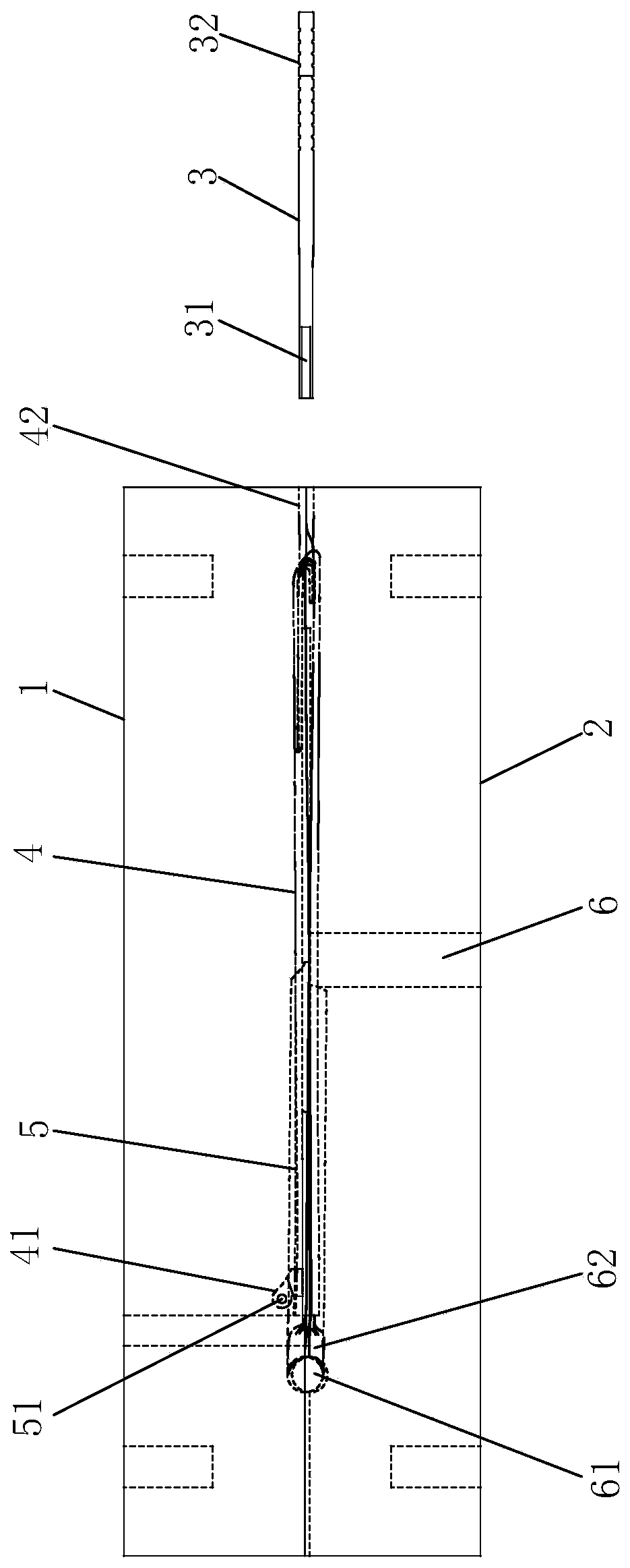
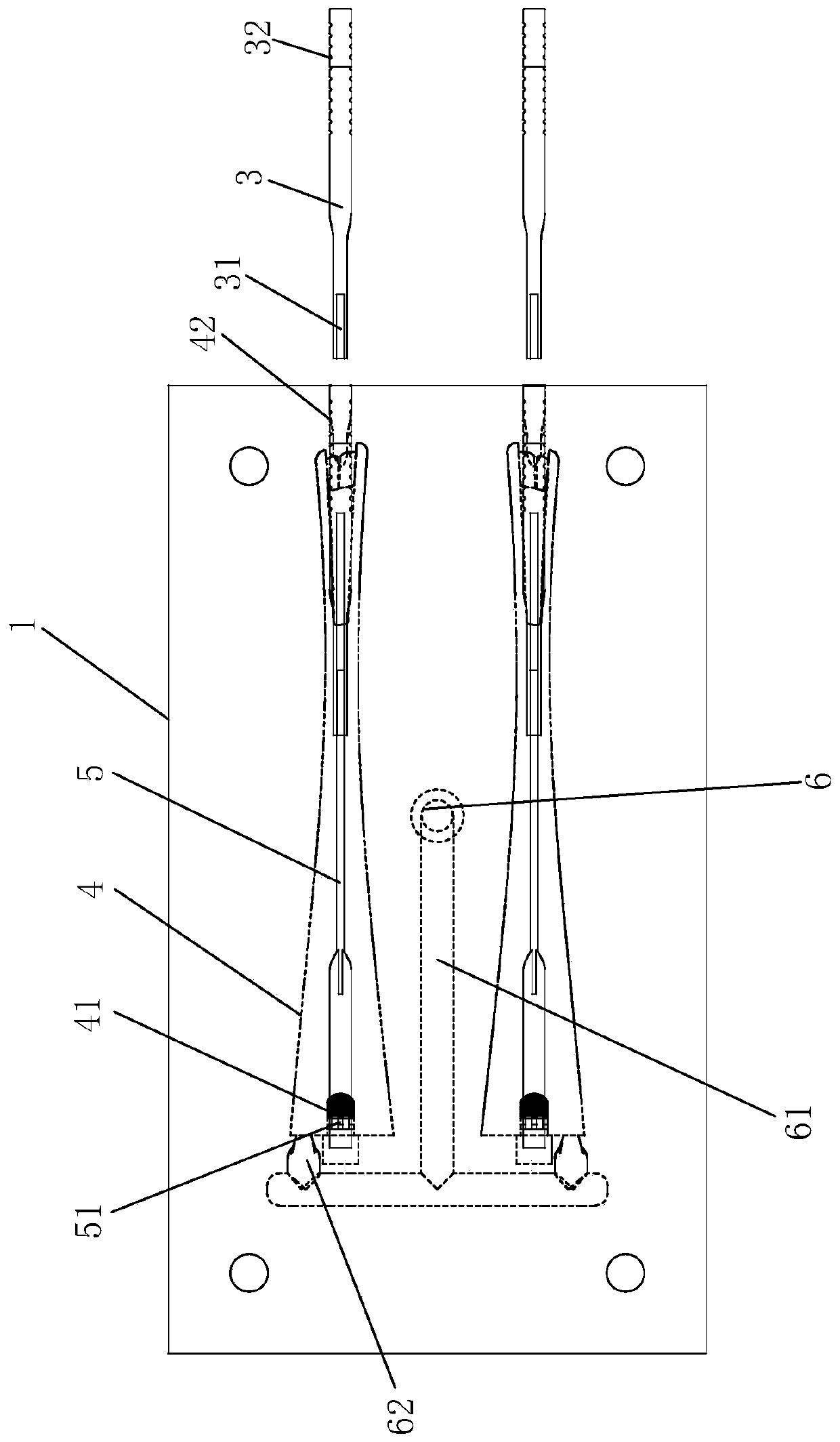
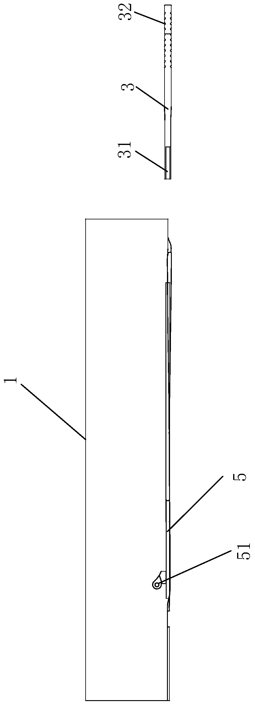
[0044] Such as Figure 1 to Figure 6 As shown, the present invention discloses a processing mold for spectacle temples, which has an upper mold 1, a lower mold 2 and a rubber tube 3, the upper mold 1 and the lower mold 2 are molded together, and between the upper mold 1 and the lower mold 2 A temple cavity 4 is formed, and the metal pole 5 is arranged in the temple cavity 4. The front end of the temple cavity 4 has a support groove 41, and the support groove 41 is inserted into the temple hinge seat 51 of the metal pole 5. The rear end of the temple cavity 4 forms a socket 42 that runs through the mold. The socket 42 is used for the insertion of the rubber tube 3. The temple cavity 4 is connected to the outside of the mold through the socket 42. The tail end of the support rod 5, so that the rubber tube 3 can extend into the temple cavity 4 when the mirror feet are processed, and is set on the tail end of the metal support rod 5, and is used to support the tail end of the meta...


PUM


Abstract

The invention discloses a glasses foot machining shaping mold. The mold is provided with an upper mold, a lower mold and a rubber tube. The upper mold and the lower mold are combined together to forma glasses foot cavity for containing a metal supporting rod. The front end of the glasses foot cavity is provided with a supporting groove for containing a glasses foot hinge base of the metal supporting rod, a slot running through the mold is formed in the rear end of the glasses foot cavity for insertion of the rubber tube, the glasses foot cavity is communicated to the exterior of the mold through the slot, according to the thickness of the rubber tube, the rubber tube can sleeve the tail end of the metal supporting rod, during glasses foot machining, the rubber tube stretches into the glasses foot cavity and sleeves the tail end of the metal supporting rod, an injection molding opening and an injection molding channel are formed on the mold, and the injection molding opening is communicated with the front end of the glasses foot cavity through the injection molding channel. The invention further discloses a corresponding machining shaping method. In the glasses foot shaping process, positioning is easy, eccentricity is not caused after shaping, machining is easy, material consumption is low, waste is avoided, the machining cost is low, and the yield is high.

Description

technical field [0001] The invention relates to the technical field of glasses processing, in particular to a processing molding mold and a processing molding method for glasses temples. Background technique [0002] Glasses are inlaid with lens lenses in the frame and worn in front of the eyes to improve vision, protect eyes or for decoration. The temples of glasses are divided into metal temples and plastic temples according to the materials used. [0003] Wherein, the plastic temple is composed of a metal pole and an outer covering layer (plastic), the outer covering layer is the main body of the mirror foot, and the metal pole supports the mirror foot and increases the strength. The front end of the metal strut near the mirror frame has a hinge seat for the mirror leg, and the hinge seat protrudes out of the outer cladding layer to realize the hinge connection between the mirror pin and the mirror frame, while the rear end of the metal strut is hidden in the outer cladd...

Claims


Application Information

Patent Timeline
Patent Type & Authority Applications(China)
IPC IPC(8): B29C45/14B29C45/26B29L12/00
CPCB29C45/14008B29C45/14336B29C45/2602B29L2012/005
Inventor 王为城
Owner 厦门立扬光学科技有限公司
Why Eureka
Try Eureka