
Multi-support multi-roller track component and track

A support component and multi-support technology, which is applied to the track composed of multi-support and multi-roller track components, and in the field of multi-support and multi-roller track components, can solve the problems of reducing the strength of the roller shaft, the accuracy of the location of the damage position, and the noise of the car body. Reduce the chance of mutual contact and wear, increase stability and continuity, and reduce noise and vibration

Pending Publication Date: 2019-11-01
ARMOR ACADEMY OF CHINESE PEOPLES LIBERATION ARMY
View PDF5 Cites 4 Cited by
  • Summary
  • Abstract
  • Description
  • Claims
  • Application Information

AI Technical Summary

Problems solved by technology

This structure has the following problems: 1) The rollers are arranged at both ends of the support. During the movement of the track shoes, before the rollers contact the ground or at the moment of contact, the roller bracket may collide with the ground (on non-strictly flat roads) Especially), it produces loud noise and strong vibration, which limits the omni-directional motion capability of the track and its platform, interferes with operation and control, increases the wear of the roller bracket and the wear of the entire track
2) The number of rollers is small (there are only 1-2 rollers on each track plate), which leads to the fact that each roller bears a large pressure, a high degree of compression, and a large degree of deformation during the track movement (roller grounding). At this time, the rollers It is no longer a regular cylindrical shape
This wear becomes extremely serious in the case of heavy loads on the platform, or after lightweight design of the track shoes
5) The top of the roller does not exceed the center line of the track pin, which may cause the adjacent track shoes to lift during the grounding movement of the roller, causing the upper surface of the track ground section to become uneven, and the road wheels moving on it will be Generate interference (the interference is more serious when the diameter of the road wheel is not much larger than the pitch of the track shoe), which in turn causes noise and vibration of the car body
In addition to the problems described in 2)-5) above, this document also has the following problems: the two rollers are respectively placed on both sides of the roller bracket, thus avoiding the problems described in 1) above, but it brings another problem at the same time. The problem is that the roller shaft is supported from both ends to the middle support, so the roller shaft becomes a two-section cantilever beam, which greatly reduces the strength of the roller shaft, that is, the middle support of the roller causes the roller pin shaft to become a cantilever beam
Although in actual motion, the "point landing" state is often deformed into a surface near the point due to the action of pressure, but this "face landing" that cannot control the shape will destroy the accuracy of the position positioning of the platform in all-round motion , thus affecting the overall working status and efficiency of the platform
At the same time, because the "face-to-ground" landing area is very small, it can still be regarded as "point-to-ground" relative to the platform as a whole, which will cause large vibration and noise during the movement of the track and its platform, and serious wear of the rollers. Poor ground adaptability, poor reliability and practicability

Method used


Image

  • Multi-support multi-roller track component and track
  • Multi-support multi-roller track component and track
  • Multi-support multi-roller track component and track

Examples


Embodiment Construction

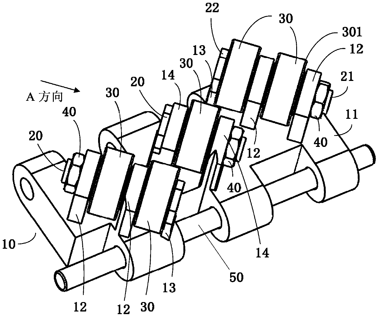
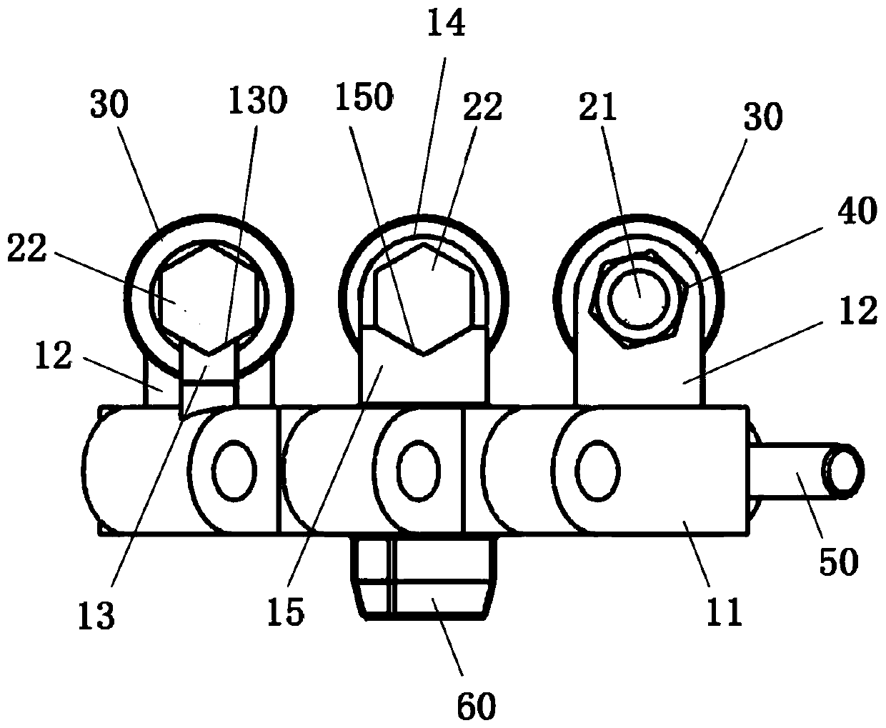
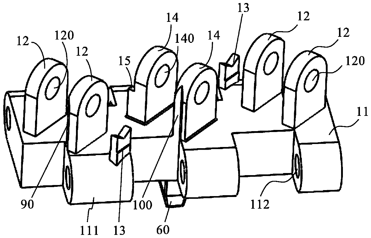
[0037] Such as Figure 1 to Figure 9 , the multi-support multi-roller track component of the present invention includes a track shoe 10, and a roller 30 is installed on the track shoe 10, wherein: the track shoe 10 includes a board body 11, a support member is provided on the board body 11, and crawler belts are provided on both sides of the board body 11. Pin 50, the track pin 50 is used to pin two adjacent track shoes 10 together ( figure 1 Only one plate body 11 is shown connected to the track pin 50); the support member includes two roller brackets 12 and a roller support 13 coaxially and sequentially separated, that is, the roller support 13 is located between the two roller supports 12 On the side, the two rollers 30 are installed on the supporting member through the roller bolts 20, and the threaded ends of the roller bolts 20 pass through the through holes 120 of the two roller brackets 12 and are screwed with the lock nuts 40. At the same time, the heads of the rolle...


PUM


Abstract

The invention discloses a multi-support multi-roller track component and a track. The track component comprises a track plate, rolling wheels are installed on the track plate, the track plate comprises a plate body, supporting components are arranged on the plate body, track pins are arranged on the two sides of the plate body, the supporting components comprise two rolling wheel supports and a rolling wheel supporting base, wherein the two rolling wheel supports and the rolling wheel supporting base are coaxially and sequentially separated from one another; the two rolling wheels are installed on the supporting components through rolling wheel bolts, the head parts of the rolling wheel bolts are arranged on positioning grooves of the rolling wheel supporting base while the threaded ends of the rolling wheel bolts penetrate through holes of the two rolling wheel supports and then are screwed with locking nuts, the rolling wheels can be rotationally arranged on screw rods of the rollingwheel bolts in a penetrating mode, the rolling wheels form bias angles relative to the track pins, one rolling wheel is arranged between the two rolling wheel supports, and the other rolling wheel isarranged between the rolling wheel supports and the rolling wheel supporting base. The track component has the advantages that the structure is compact, the first time contact of the rolling wheels can be kept, the collision abrasion is small, the service life is long, the noise and vibration are reduced, the adaptability of various road surfaces is high, and the like.

Description

technical field [0001] The invention relates to a crawler structure, in particular to a multi-support and multi-roller track member suitable for a crawler-type omnidirectional mobile platform, a crawler-type high-efficiency steering platform, etc., and a crawler composed of a multi-support and multi-roller track member. Background technique [0002] Omnidirectional mobile platform, also known as omnidirectional mobile platform, refers to a mobile platform that can move along the X-axis and Y-axis on a two-dimensional plane, and can rotate around its own center, and can complete the above compound movements. According to the shape and structure of the walking mechanism, the omni-directional mobile platform can be divided into a wheel-type omni-directional mobile platform and a crawler-type omni-directional mobile platform. The walking mechanism of the wheeled all-round mobile platform mainly includes Mecanum wheel (moveable caster), Transwheel (express robot vehicle), Orthogo...

Claims


Application Information

Patent Timeline
Patent Type & Authority Applications(China)
IPC IPC(8): B62D55/08
CPCB62D55/08
Inventor 张豫南房远华俊刘艳华杨怀彬张传杨周野董政闫猛飞
Owner ARMOR ACADEMY OF CHINESE PEOPLES LIBERATION ARMY
Learn More