
Pneumatic layout for improving transverse lateral coupling characteristics of hypersonic flight vehicle

A hypersonic and aerodynamic layout technology, applied to aircraft, supersonic aircraft, motor vehicles, etc., can solve problems such as flight test failure, reduced flight angle of attack, and lift reduction, and achieve improved lateral coupling at large angles of attack characteristics, effects of eliminating lateral instability and improving lateral stability

Inactive Publication Date: 2019-11-01
CHINA ACAD OF AEROSPACE AERODYNAMICS
View PDF5 Cites 2 Cited by
  • Summary
  • Abstract
  • Description
  • Claims
  • Application Information

AI Technical Summary

Problems solved by technology

The first failure was due to a higher than expected yaw, accompanied by an uncontrollable roll
The second flight test lowered the flight angle of attack and flew under stable aerodynamic control for 3 minutes, but lost contact with the ground again when trying to pull up. out of control
[0005] From the flight test results of HTV-2, it can be seen that the first flight test was probably caused by the instability of the lateral system under the aileron control at a high angle of attack, and the second flight test reduced the flight angle of attack to achieve Improvement, but the lift force also decreases with the decrease of the angle of attack, which reduces the flight altitude and brings about a more severe problem of thermal environment, which leads to the failure of the second flight test

Method used


Image

  • Pneumatic layout for improving transverse lateral coupling characteristics of hypersonic flight vehicle
  • Pneumatic layout for improving transverse lateral coupling characteristics of hypersonic flight vehicle
  • Pneumatic layout for improving transverse lateral coupling characteristics of hypersonic flight vehicle

Examples


Embodiment Construction

[0023] Below in conjunction with example, illustrate the specific embodiment of the present invention.

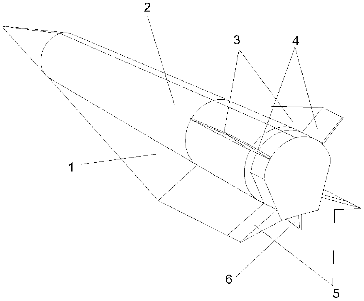
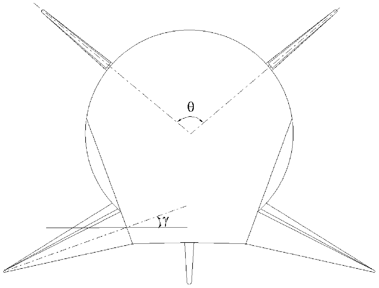
[0024] Such as Figure 2-4 As shown, an aerodynamic layout for improving the lateral coupling characteristics of a hypersonic vehicle of the present invention includes a pair of wings 1, a fuselage 2, a pair of V tails 3, a pair of V tail trailing edge rudders 4, a pair of The rear edge of the wing rudder 5 and a pelvic fin 6; the wing 1 is symmetrically installed below the fuselage 2, the V tail 3 is symmetrically installed above the rear of the fuselage 2, and the pelvic fin 6 is installed behind the bottom of the fuselage 2; the rear edge of the wing 1 Wing trailing edge rudders 5 are installed respectively; V tail trailing edge rudders 4 are respectively installed on the trailing edge of V tail 3; wing trailing edge rudders 5 and V tail trailing edge rudders 4 are the aerodynamic control rudder surfaces of the aircraft.

[0025] The fuselage is generated according to t...


PUM


Abstract

The invention discloses a pneumatic layout for improving the transverse lateral coupling characteristics of a hypersonic flight vehicle. The surface symmetrical lift-drag ratio pneumatic layout adopting the design comprises wings (1), a fuselage (2), V tails (3), V tail trailing edge rudders (4), wing trailing edge rudders (5) and a ventral fin (6), wherein the wings (1) are symmetrically installed under the fuselage (2), the V tails (3) are symmetrically installed on the rear portion of the fuselage (2), the ventral fin (6) is installed at the rear portion of the bottom of the fuselage (2), the rear edges of the wings (1) are provided with the wing trailing edge rudders (5), the rear edge of the V tail (3) is provided with the V tail trailing edge rudders (4), and the wing trailing edge rudders (5) and the V tail trailing edge rudders (4) are pneumatic operation control surfaces. By adopting the pneumatic design, the lateral instability caused by the rolling operation coupling effectunder a large attack angle of an existing pneumatic layout can be very effectively eliminated, so that the closed-loop stability in the transverse lateral direction under the large attack angle is improved.

Description

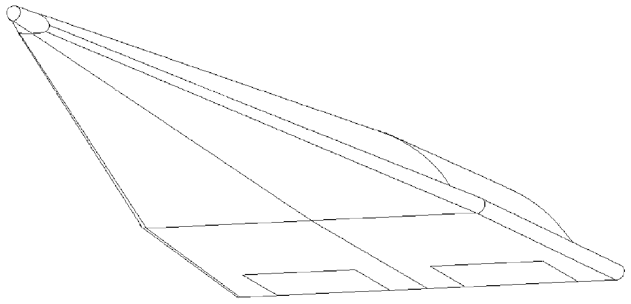
technical field [0001] The invention relates to an aerodynamic layout of a hypersonic aircraft, which is applicable to hypersonic flight. Background technique [0002] figure 1 It is a three-dimensional schematic diagram of the aerodynamic layout of an existing hypersonic vehicle. The layout of a typical hypersonic high-lift-drag ratio surface symmetric aircraft represented by a waverider configuration mainly changes the direction of velocity through changes in the direction of lift, so the ability to change the angle of attack longitudinally and roll laterally determines its longitudinal and lateral flight Performance, which requires the design of the control layout, so that the aircraft has the control capability of a large range of angle of attack and agile roll performance. As the first hypersonic flight test of the aerodynamic shape of the waverider, HIFiRE 4 has carried out exploratory research on the control layout design and flight stability control of the high lif...

Claims


Application Information

Patent Timeline
Patent Type & Authority Applications(China)
IPC IPC(8): B64C30/00B64C3/14B64C9/00
CPCB64C3/14B64C9/00B64C30/00
Inventor 陈冰雁徐国武刘哲关发明艾邦成李锋
Owner CHINA ACAD OF AEROSPACE AERODYNAMICS
Learn More