Universal zero-gravity unloading device

An unloading device, zero-gravity technology, applied in the simulation device of space navigation conditions, transportation and packaging, space navigation equipment, etc., can solve the problems of large resistance, increased unloading friction, poor straightness, etc. Simple, improved stability, good versatility

Active Publication Date: 2019-11-01
XIAN INSTITUE OF SPACE RADIO TECH
View PDF5 Cites 4 Cited by
  • Summary
  • Abstract
  • Description
  • Claims
  • Application Information

AI Technical Summary

Problems solved by technology

Due to the complex deployment form of this type of antenna, it is necessary to accurately unload the center of mass of the reflector. Since the unloading of the center of mass requires a counterweight frame to configure the center of mass, this leads to a large weight of the deployed part of the antenna.
[0003] The unloading of the existing slide rails leads to deformation of the slide rails under the action of large-mass gravity, and the resistance is relatively large
In this way, when the antenna rotates under the drive of the mechanism, the motor acts on the harmonics to cause elastic deformation and gradually increase the output torque. When the torque is greater than the resistance torque, the antenna can rotate. After the harmonic elastic torque is released, it will stop rotating and continue. Accumulate elastic potential energy, so that the antenna unfolds intermittently and rotates, which has a great impact on product safety and test accuracy, and cannot well simulate the zero-gravity deployment movement on orbit, so a universal zero-gravity unloading device is proposed
[0004] The existing "A Zero Gravity Suspension Type Deployment Test Device" patent, the movement of the unloading point during the antenna unloading process is linear sliding, and the unloading track is deformed due to large deformation during the antenna unloading process. When the unloading weight is large, the unloading resistance is greater and cannot meet the antenna deployment requirements

Method used


Image

  • Universal zero-gravity unloading device
  • Universal zero-gravity unloading device
  • Universal zero-gravity unloading device

Examples


Embodiment Construction

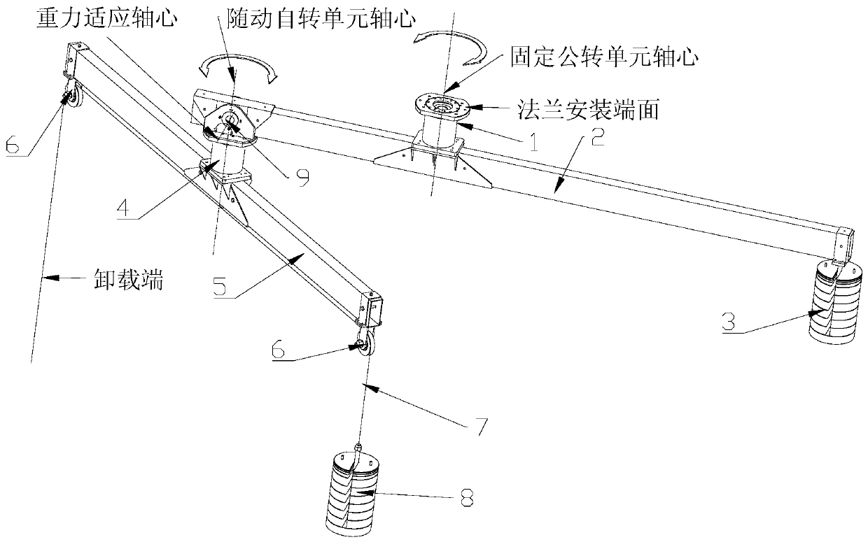
[0036] Such as figure 1 As shown, a planetary trajectory zero-gravity unloading device 10 includes a fixed revolution unit 1, a revolution load beam 2, a balance method weight 3, a follow-up rotation unit 4, a rotation load beam 5, a fixed pulley 6, and an unloading cable 7. Dynamic code 8, gravity adaptation axis 9, etc.

[0037] combine Figure 6 , the fixed part of the fixed revolution unit 1 is fixed at the working position, the rotating part is fixed on the revolution bearing beam 2, and the rotating part can rotate around the axis of the unit.

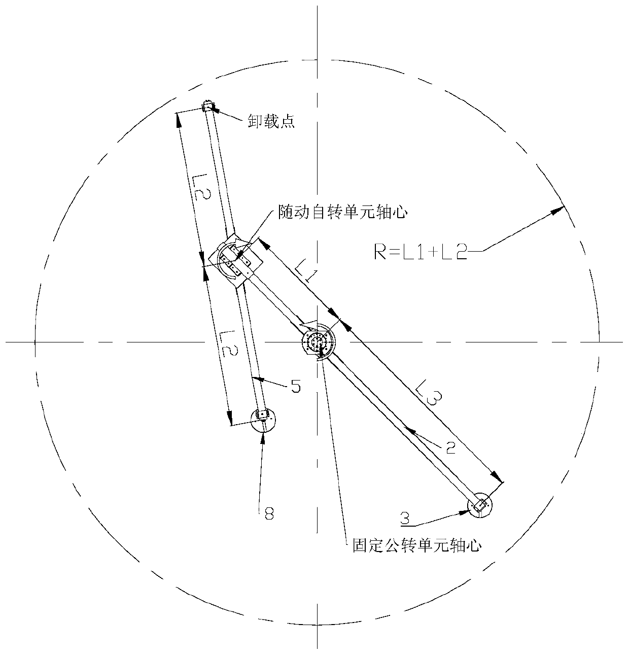
[0038] The revolution bearing beam 2 is a square tube profile, one end of which is connected to the fixed part of the follow-up rotation unit 4, and the other end is connected to the balance weight 3; the distance between the axis of the fixed revolution unit 1 and the follow-up rotation unit 4 is the axis L1.

[0039] The self-rotating load beam 5 is a square tube profile, and fixed pulleys 6 are arranged at both ends, and th...


PUM


Abstract

The invention relates to a universal zero-gravity unloading device. The universal zero-gravity unloading device is used for realizing satellite-borne antenna ground-based simulation deployment and isdeveloped aiming at meeting the requirements of large antenna unloading capacity and high unloading precision requirements, rotating is adopted to replace sliding, a balance weight is adopted to pre-balance the gravitational torque of a revolution bearing beam relative to the center of a fixed revolution unit, so that it is guaranteed that the device is always in a vertical state, a gravity adaptive shaft is designed to guarantee that the axis of a servo autorotation unit is automatically vertical, and therefore the unloading stability is remarkably improved; by means of the planetary double-rotation motion self-adaptive unloading point two-dimensional motion, three-dimensional space motion is completed through cooperation of vertical motion of an unloading cable, overlapping type antennascan be realized, simulation zero-gravity deployment of overlapped antennas and other antennas meeting the track can be realized, and the universality is good; and the device is simple to install anddebug, convenient to transport and suitable for fast use in various occasions.

Description

technical field [0001] The invention relates to a universal zero-gravity unloading device, which is used to realize the ground simulation deployment of a spaceborne antenna, and belongs to the technical field of antenna mechanisms. Background technique [0002] The development of the deployable overlapping antenna, its deployment trajectory and form are as follows: image 3 , Figure 4 . Due to the complex deployment form of this type of antenna, it is necessary to accurately unload the center of mass of the reflector. Since the unloading of the center of mass requires a counterweight frame to configure the center of mass, this leads to a large weight of the deployed part of the antenna. [0003] The unloading of the existing slide rails causes the deformation of the slide rails under the action of large mass gravity, and the resistance is relatively large. In this way, when the antenna rotates under the drive of the mechanism, the motor acts on the harmonics to cause elas...

Claims


Application Information

Patent Timeline
IPC IPC(8): B64G7/00
CPCB64G7/00
Inventor 薛兆璇侯健陈富帅陶啸赵颖柯昌文栗卫华董翔
Owner XIAN INSTITUE OF SPACE RADIO TECH
Why Eureka
Try Eureka