Clutter map principle-based radar clutter signal suppression method and radar detection system

A clutter signal, clutter map technology, applied in radio wave measurement systems, radio wave reflection/re-radiation, measurement devices and other directions, can solve the problem of not being able to guarantee at the same time, and achieve the effect of improving target detection capabilities

Active Publication Date: 2019-11-01
四川九洲防控科技有限责任公司
View PDF10 Cites 5 Cited by
  • Summary
  • Abstract
  • Description
  • Claims
  • Application Information

AI Technical Summary

Problems solved by technology

Although the high-order FIR filter has a very low passband cut-off frequency, it still has a certain inhibitory effect on low-speed targets
Using the above two methods cannot guarantee the detection of low-speed targets while suppressing low-speed motion clutter

Method used


Image

  • Clutter map principle-based radar clutter signal suppression method and radar detection system
  • Clutter map principle-based radar clutter signal suppression method and radar detection system
  • Clutter map principle-based radar clutter signal suppression method and radar detection system

Examples


Embodiment 1

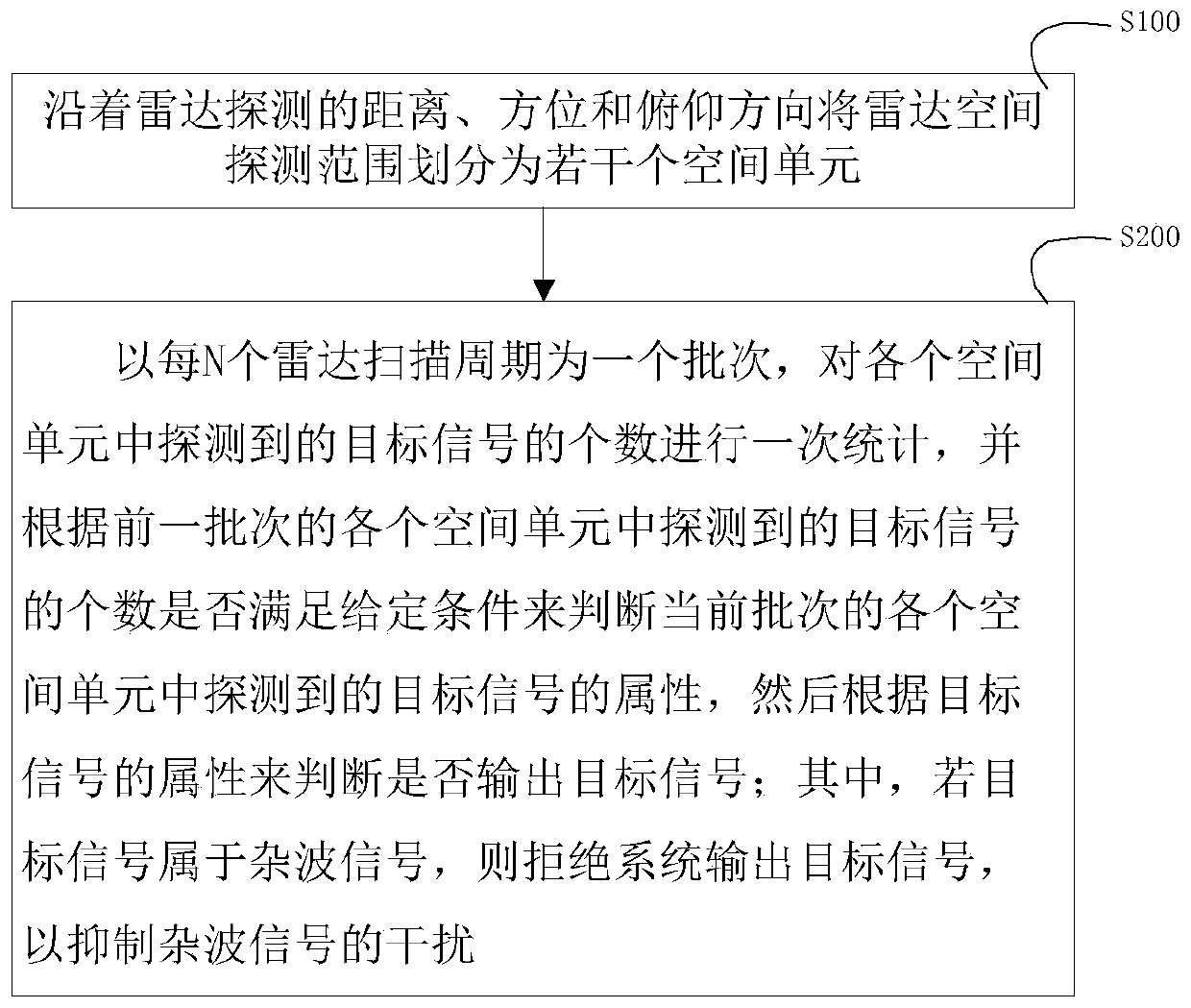
[0042] Such as image 3 As shown, the present invention aims to provide a new method for suppressing radar clutter signals. The method mainly includes the following steps:

[0043] S100, dividing the radar spatial detection range into several spatial units along the radar detection distance, azimuth and elevation direction;

[0044] S200, taking every N radar scanning cycles as a batch, making a statistics on the number of target signals detected in each space unit, and according to the number of target signals detected in each space unit in the previous batch Whether the given conditions are met is used to judge the attributes of the target signals detected in each spatial unit of the current batch, and then it is judged whether to output the target signals according to the attributes of the target signals.

[0045] Wherein, if the target signal is a clutter signal, the system is rejected to output the target signal, so as to achieve the purpose of suppressing the clutter s...

Embodiment 2

[0067] Correspondingly, the present invention also provides a radar detection system for implementing the above method. Such as Figure 8 As shown, in this embodiment, the radar detection system may be composed of a transmitting antenna, a receiving antenna, a transmitting component, a frequency synthesis component, a receiving component, a signal processing component, a data processing component and a control terminal. The connection relationship of these components can be found in the appendix Figure 8 . in:

[0068] Control terminal: in the clutter map speed control mode, send the clutter map speed control mode and Doppler channel control commands to the data processing component;

[0069] Data processing component: receive the control command issued by the operation terminal and forward it to the signal processing component;

[0070] Signal processing component: receive the clutter map velocity control command issued by the data processing component, establish a clutt...

Embodiment 3

[0082] The method for suppressing radar clutter signals and the radar detection system provided by the present invention are further illustrated below with examples.

[0083] Such as Figure 4 As shown, it is a two-dimensional plane scanning diagram of a certain radar (here the elevation direction is omitted). The radar has a total of 1000 distance units in the working distance, and every 3 degrees in the 360-degree azimuth is divided into an azimuth unit, so there are 120 azimuth units in total. That is, the radar detection spatial range is divided into 120*1000 spatial units (the product of the number of azimuth units and the number of distance units)

[0084] In order to adopt ping-pong operation, the radar detection system divides the internal storage space into two basic point ping-pong storage areas: storage area A and storage area B, where storage area A and storage area B have storage spaces of 120*1000 storage units respectively.

[0085] Assuming that the radar is ...


PUM


Abstract

The invention provides a clutter map principle-based radar clutter signal suppression method and a radar detection system. The method comprises the following steps of S100, dividing a radar space detection range into a plurality of space units along radar detection distance, direction and pitching direction; and S200, counting numbers of target signals detected in each space unit in one time by taking each N radar scanning periods as a batch, judging attribute of the target signal detected in each space unit in current batch according to the situation whether the numbers of the target signal detected in each space unit in previous batch conform to a given condition or not, judging whether the target signal is output or not according to the attribute of the target signal, and rejecting thesystem to output the target signal so as to prevent interference of a clutter signal if the target signal belongs to the clutter signal.

Description

technical field [0001] The invention relates to the technical field of radar signal processing, in particular to a radar clutter signal suppression method and a radar detection system based on the clutter map principle. Background technique [0002] In recent years, with the widespread use of low-speed and small UAVs, higher performance requirements have been put forward for radars that can detect low-speed targets. Due to the influence of environmental noise, low-speed targets and surrounding environment clutter characteristics have strong Similarity, in a complex environment, it is impossible to effectively distinguish low-speed targets from the environment. [0003] Traditional MTD radar suppresses low-speed motion clutter mainly by using MTI filter before MTD, such as first-order, second-order, or multi-order cancellation filters, and the frequency response of third-order cancellation filters is as follows: figure 1 shown. [0004] In an environment with high requireme...

Claims


Application Information

Patent Timeline
Patent Type & Authority Applications(China)
IPC IPC(8): G01S7/292G01S7/41G01S7/02G01S13/50
CPCG01S7/023G01S7/2927G01S7/414G01S7/415G01S13/50
Inventor 何文洲李春林赵怀坤程泉彭杰
Owner 四川九洲防控科技有限责任公司
Why Eureka
Try Eureka