
Testing device for positioning accuracy of articulated robot

A technology of robot positioning and testing device, applied in the direction of measuring device, instrument, manipulator, etc., can solve the problems of difficult self-fixation and irregular wrapping

Pending Publication Date: 2019-11-01
SHAOYANG UNIV
View PDF4 Cites 1 Cited by
  • Summary
  • Abstract
  • Description
  • Claims
  • Application Information

AI Technical Summary

Problems solved by technology

[0005] The invention provides a testing device for the positioning accuracy of a joint robot, which solves the problems of non-standard bandaging and difficult self-fixation after anorectal disease operation

Method used


Image

  • Testing device for positioning accuracy of articulated robot
  • Testing device for positioning accuracy of articulated robot
  • Testing device for positioning accuracy of articulated robot

Examples


no. 1 example

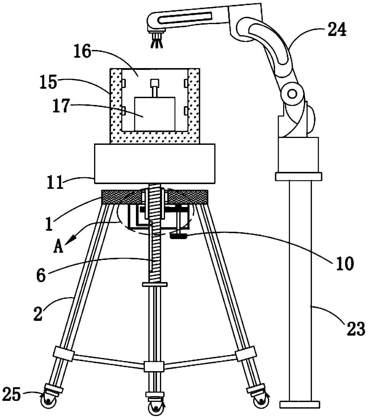
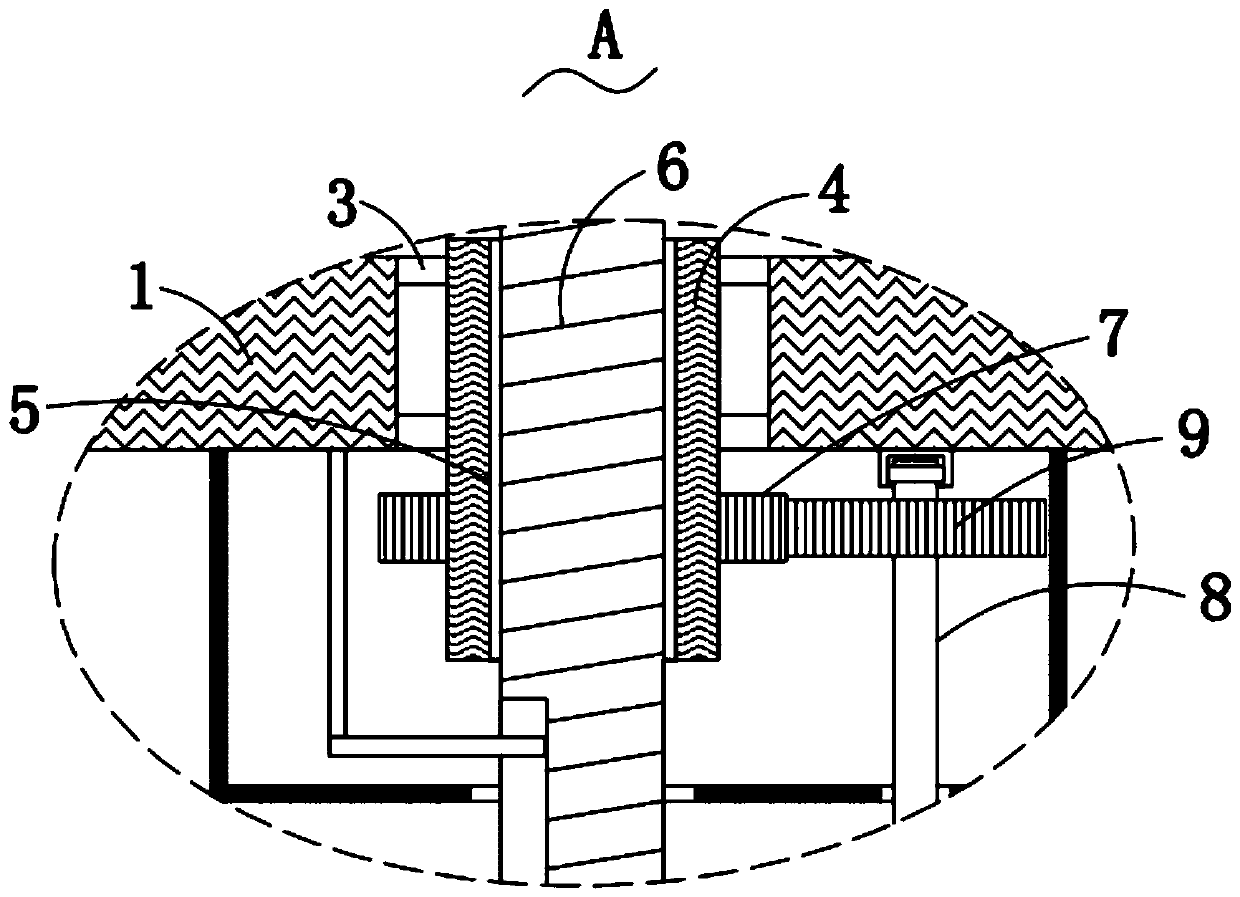
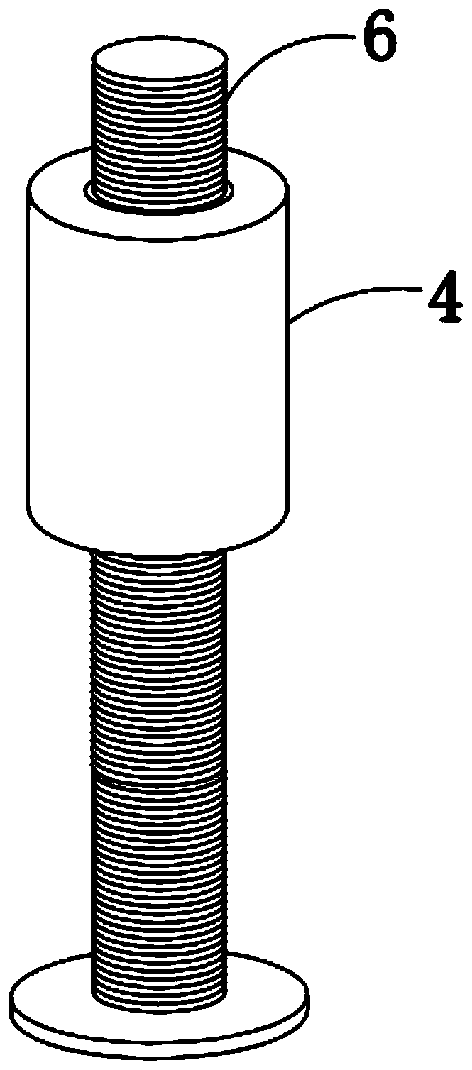
[0028] Please refer to Figure 1-3 , in the first embodiment of the present invention, the test device for the positioning accuracy of the joint robot includes: a base 1; three support rods 2, and the three support rods 2 are all fixedly installed on the bottom of the base 1; mounting holes 3. The installation hole 3 is provided on the top of the base 1, the installation hole 3 is located between the three support rods 2; the lifting structure, the lifting mechanism is fixed on the base 1, the The lifting mechanism includes a connecting shaft 4, a threaded hole 5, a threaded rod 6, a first gear 7, a rotating rod 8, a second gear 9 and a handle 10; a placement box 11, and the placement box 11 is located above the base 1; Test box 15, said test box 15 is fixedly installed on the top of said placement box 11; Test cavity 16, said test cavity 16 is offered on said test box 15, and the top of said test cavity 16 is an open structure; standard Block 17, the standard block 17 is pla...

no. 2 example

[0048] Please refer to Figure 4-6 , based on the test device for the positioning accuracy of the articulated robot provided in the first embodiment of the present invention, the test device for the positioning accuracy of the articulated robot provided in the second embodiment of the present invention, the difference is that the test device for the positioning accuracy of the articulated robot also includes Installing groove 12, described installing groove 12 is offered at the bottom of described placing box 11, and the top end of described threaded rod 6 extends in described installing groove 12, and described placing box 11 is provided with fixing cavity 13, and described fixing The top of the cavity 13 is an open structure, the fixed cavity 13 is provided with a positioning plate 14, and the test box 15 is fixedly installed on the top of the positioning plate 14;

[0049] The fixed cavity 13 is provided with a rotating mechanism, the rotating mechanism includes a rotating ...


PUM


Abstract

The invention provides a testing device for positioning accuracy of an articulated robot. The test device for positioning accuracy of the joint robot comprises the following parts of a base; three support rods all fixedly mounted on the bottom of the base; a mounting hole defined on the top of the base and located among the three support rods; a lifting structure fixedly mounted on the base and comprising a connecting shaft, a threaded hole, a threaded rod, a first gear, a rotating rod, a second gear and a handle; and a placement box. The testing device provided by the invention is simple in structure, convenient to operate, and economical and practical, facilitates convenient adjustment of the height position of the test box, and can control the rotation of the test box, so that the positioning accuracy can be tested under different heights and rotation states to obtain different data for analysis and calculation, thereby greatly improving the accuracy of the positioning accuracy test.

Description

technical field [0001] The invention relates to the field of testing equipment, in particular to a testing device for the positioning accuracy of a joint robot. Background technique [0002] With the rapid development of mechanical automation, mechanical automation is slowly applied in industrial production. Various robots are the main equipment to replace manual transportation and processing of workpieces. During the movement of robots, in order to ensure the accuracy of workpiece processing, for The repetitive positioning accuracy of robot movement is high. To evaluate the performance of a robot's pose accuracy, it is usually tested with a special tester. Through the comparative analysis of the test data, the performance of the robot can be judged. [0003] In the prior art, a test device for robot positioning accuracy is disclosed, which includes a test body and a standard cube. The test body includes six laser ranging sensors for measurement, and the six laser ranging se...

Claims


Application Information

Patent Timeline
IPC IPC(8): G01S17/06G01S17/08B25J19/00
CPCG01S17/06G01S17/08B25J19/0095
Inventor 李冬英梁睿李梦奇
Owner SHAOYANG UNIV
Learn More