
An Optical Frequency Comb Flatness Control Method Based on Optical Filtering

A control method and optical filtering technology, applied in lasers, laser parts, electrical components, etc., can solve the problems of poor flatness, high noise, limited spectral components, etc., and achieve the effects of convenient operation, simple structure and great flexibility

Active Publication Date: 2020-07-14
THE 44TH INST OF CHINA ELECTRONICS TECH GROUP CORP +1
View PDF7 Cites 0 Cited by
  • Summary
  • Abstract
  • Description
  • Claims
  • Application Information

AI Technical Summary

Problems solved by technology

Several methods have their own advantages and disadvantages. Microcavity technology has the characteristics of small size and high repetition frequency, but it is noisy and the repetition frequency tuning range is limited; quantum dot mode-locking technology has the advantages of wide spectrum and compact structure, but the repetition frequency tuning The range is limited, and it is difficult to synchronize with the external reference light; the electrical cascade modulation technology has the characteristics of a large repetition frequency tuning range and convenient synchronization with the external reference light, but the system is relatively complicated
The most important thing is that the high repetition rate optical frequency combs produced by several methods all have symmetrical spectral curve distribution, but they all have the characteristic of poor flatness, which leads to limited spectral components that can be used, which seriously limits the high repetition rate optical frequency comb. Broader applications of frequency combs

Method used


Image

  • An Optical Frequency Comb Flatness Control Method Based on Optical Filtering
  • An Optical Frequency Comb Flatness Control Method Based on Optical Filtering
  • An Optical Frequency Comb Flatness Control Method Based on Optical Filtering

Examples


Embodiment Construction

[0033] In order to make the purpose, technical solutions and advantages of the present invention clearer, the technical solutions in the embodiments of the present invention will be clearly and completely described below in conjunction with the accompanying drawings. Obviously, the described embodiments are only part of the embodiments of the present invention, and Not all examples.

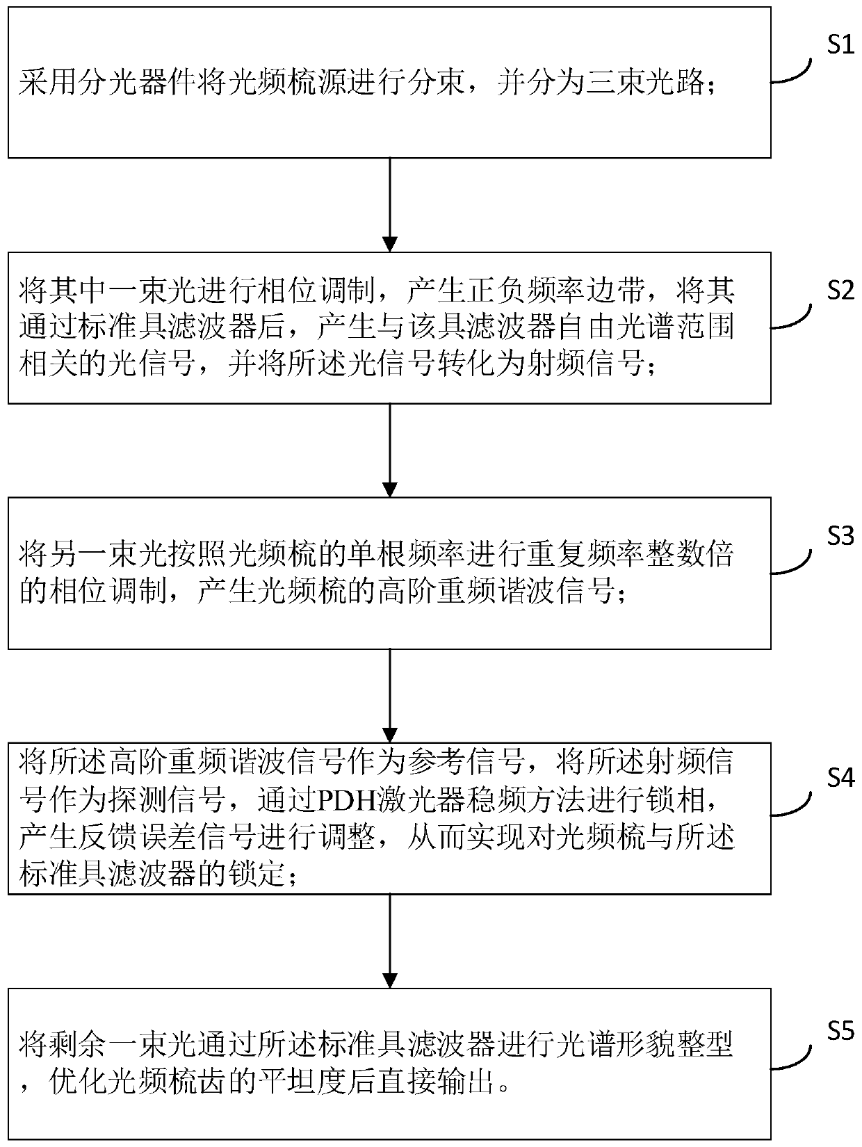
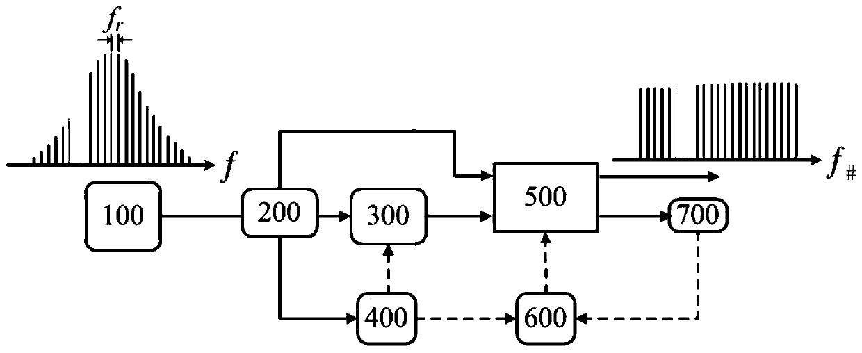
[0034] In one embodiment, as figure 1 Shown, the optical frequency comb flatness control method based on optical filtering of a kind of all-fiber structure, described method may comprise the following steps:

[0035] S1. The optical frequency comb source is split by a splitting device and divided into three beam paths;

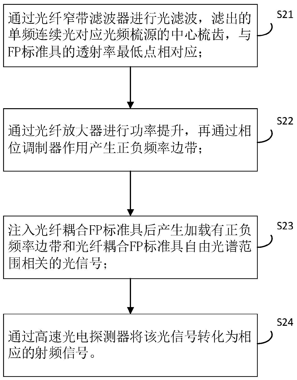
[0036] S2. Perform phase modulation on one of the beams of light to generate positive and negative frequency sidebands, pass it through the etalon filter, generate an optical signal related to the free spectral range of the filter, and convert the optical signal into a radio fre...


PUM


Abstract

The invention belongs to the ultrafast optics technology field and particularly relates to an optical frequency comb flatness control method based on optical filtering. The method comprises steps thatan optical frequency comb source is subjected to beam splitting by utilizing a beam splitting device; one of the light beams is subjected to phase modulation to generate positive and negative frequency sidebands, after the sidebands pass through an etalon filter, an optical signal related to the free spectral range of the etalon filter is generated, and the optical signal is converted into a radio frequency signal; another beam is subjected to phase modulation at an integer multiple of the repetition frequency according to the single frequency of an optical frequency comb to generate a high-order re-frequency harmonic signal of the optical frequency comb; the high-order re-frequency harmonic signal is taken as a reference signal, the radio frequency signal is taken as a detection signal,phase locking is performed by a PDH laser device frequency stabilization method, a feedback error signal is generated for adjustment, and the optical frequency comb and the etalon filter are locked; remaining light beams are subjected to spectral shape shaping through the etalon filter, and direct output is performed after flatness of optical comb teeth is optimized. The method is advantaged in that the high re-frequency optical frequency comb with high flatness can be effectively outputted.

Description

technical field [0001] The invention belongs to the technical field of ultrafast optics, and in particular relates to a method for controlling the flatness of an optical frequency comb based on optical filtering. Background technique [0002] Femtosecond optical frequency combs have ultra-fast time resolution and ultra-high frequency accuracy, providing a larger platform for scientific research to study and explore natural laws. At the same time, each optical frequency "comb tooth" in the femtosecond optical frequency comb precisely controlled in the time-frequency domain has the narrow linewidth characteristic of a single longitudinal mode continuous laser, which is equivalent to having 10 5 or 10 6 A frequency stabilized continuous laser. After more than ten years of development, it has become an ideal light source for scientific research such as precise spectral measurement, determination of fundamental physical constants, astronomical measurement, and quantum optical m...

Claims


Application Information

Patent Timeline
Patent Type & Authority Patents(China)
IPC IPC(8): H01S3/13
CPCH01S3/1304
Inventor 王超瞿鹏飞孙力军
Owner THE 44TH INST OF CHINA ELECTRONICS TECH GROUP CORP
Features
  • Generate Ideas
  • Intellectual Property
  • Life Sciences
  • Materials
  • Tech Scout
  • Unparalleled Data Quality
  • Higher Quality Content
  • 60% Fewer Hallucinations
Learn More