
A flatness control device for optical frequency comb based on optical filtering

A control device and optical filtering technology, which is applied in the field of ultrafast optics, can solve problems such as poor flatness, large noise, and limited spectral components, and achieve the effects of convenient operation, great flexibility, and simple structure

Active Publication Date: 2020-07-14
THE 44TH INST OF CHINA ELECTRONICS TECH GROUP CORP +1
View PDF10 Cites 0 Cited by
  • Summary
  • Abstract
  • Description
  • Claims
  • Application Information

AI Technical Summary

Problems solved by technology

Several methods have their own advantages and disadvantages. Microcavity technology has the characteristics of small size and high repetition frequency, but it is noisy and the repetition frequency tuning range is limited; quantum dot mode-locking technology has the advantages of wide spectrum and compact structure, but the repetition frequency tuning The range is limited, and it is difficult to synchronize with the external reference light; the electrical cascade modulation technology has the characteristics of a large repetition frequency tuning range and convenient synchronization with the external reference light, but the system is relatively complicated
The most important thing is that the high repetition rate optical frequency combs produced by several methods all have symmetrical spectral curve distribution, but they all have the characteristic of poor flatness, which leads to limited spectral components that can be used, which seriously limits the high repetition rate optical frequency comb. Broader applications of frequency combs

Method used


Image

  • A flatness control device for optical frequency comb based on optical filtering
  • A flatness control device for optical frequency comb based on optical filtering
  • A flatness control device for optical frequency comb based on optical filtering

Examples


Embodiment Construction

[0024] In order to make the purpose, technical solutions and advantages of the present invention clearer, the technical solutions in the embodiments of the present invention will be clearly and completely described below in conjunction with the accompanying drawings. Obviously, the described embodiments are only part of the embodiments of the present invention, and Not all examples.

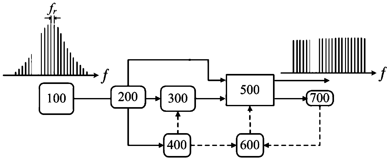
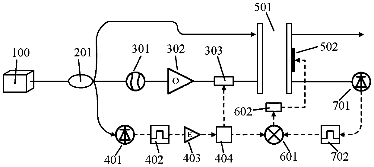
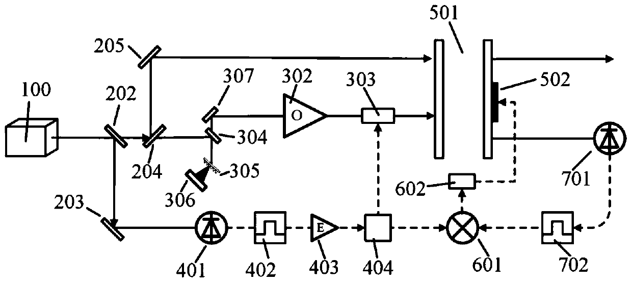
[0025] like figure 1 , in one embodiment, an optical frequency comb flatness control device based on optical filtering with an all-fiber structure, the device may include the following structure, including an optical frequency comb source 100, a beam splitting module 200, and a phase modulation module 300 , repeated frequency harmonic detection module 400, etalon filter module 500, phase-lock control module 600 and phase-lock detection module 700; wherein, the optical frequency comb source 100 is respectively connected with etalon filter module 500 after beam splitting module 200 , a phase modul...


PUM


Abstract

The invention belongs to the ultrafast optical technology field and particularly relates to an optical frequency comb flatness control device based on optical filtering. The device includes an opticalfrequency comb source, a beam splitting module, a phase modulation module, a repetitive frequency harmonic detecting module, an etalon filtering module, a phase locking control module and a phase locking detecting module, wherein the optical frequency comb source is respectively connected with the etalon filtering module, the phase modulation module and the repetitive frequency harmonic detectingmodule after passing through the beam splitting module, the phase modulation module is sequentially connected with the etalon filtering module, the phase locking detecting module and the phase locking control module, the repetitive frequency harmonic detecting module is respectively connected with the phase modulation module and the phase locking control module, and the phase locking control module is connected with the repetitive frequency harmonic detecting module. The device is advantaged in that the optical frequency comb teeth and an etalon filter are locked by utilizing the phase locking control and detecting modules, etalon filtering characteristics are utilized to form a transmission curve complementary to the optical frequency comb spectral curve, control optimization of flatnessof the optical frequency comb is effectively realized, no additional light source reference is needed, and the structure is simple.

Description

technical field [0001] The invention belongs to the technical field of ultrafast optics, and in particular relates to an optical frequency comb flatness control device based on optical filtering. Background technique [0002] Femtosecond optical frequency combs have ultra-fast time resolution and ultra-high frequency accuracy, providing a larger platform for scientific research to study and explore natural laws. At the same time, each optical frequency "comb tooth" in the femtosecond optical frequency comb precisely controlled in the time-frequency domain has the narrow linewidth characteristic of a single longitudinal mode continuous laser, which is equivalent to having 10 5 or 10 6 A frequency stabilized continuous laser. After more than ten years of development, it has become an ideal light source for scientific research such as precise spectral measurement, determination of fundamental physical constants, astronomical measurement, and quantum optical manipulation. It i...

Claims


Application Information

Patent Timeline
Patent Type & Authority Patents(China)
IPC IPC(8): H01S3/13
CPCH01S3/1304
Inventor 王超瞿鹏飞孙力军
Owner THE 44TH INST OF CHINA ELECTRONICS TECH GROUP CORP
Features
  • Generate Ideas
  • Intellectual Property
  • Life Sciences
  • Materials
  • Tech Scout
  • Unparalleled Data Quality
  • Higher Quality Content
  • 60% Fewer Hallucinations
Learn More