
Multiplexed KVM optical transmission system, cascaded optical transmitter and receiver and optical interface card

A technology of multiplexing and optical transceiver, which is applied in the selection device of multiplexing system, TV system adapted to optical transmission, cable transmission adaptation, etc., can solve the problem of waste of optical fiber resources, etc. The effect of power consumption, construction difficulty and cost reduction

Active Publication Date: 2019-11-01
BEIJING DIGIBIRD TECH CO LTD
View PDF8 Cites 2 Cited by
  • Summary
  • Abstract
  • Description
  • Claims
  • Application Information

AI Technical Summary

Problems solved by technology

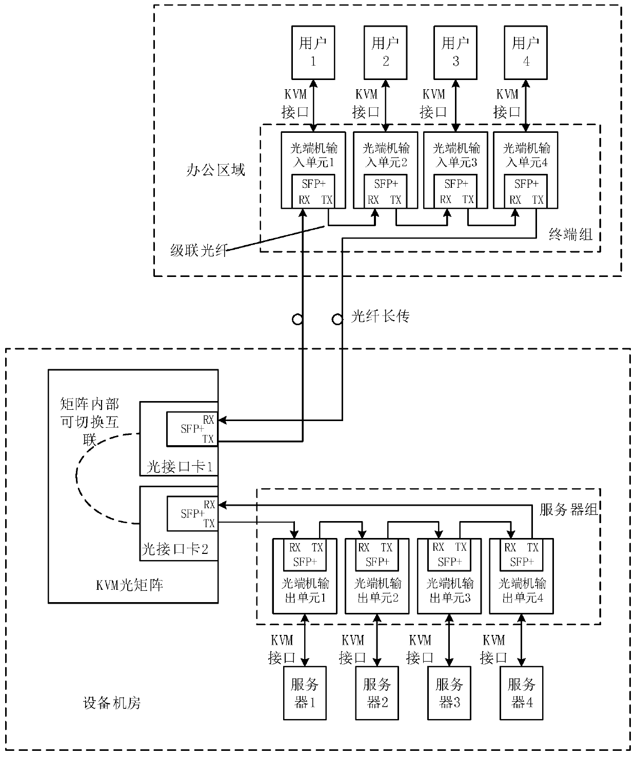
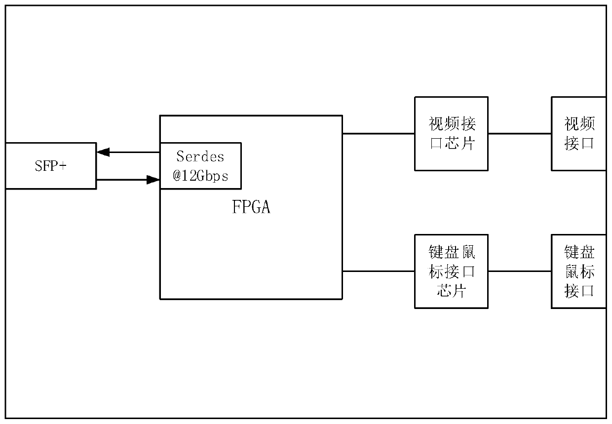
[0005] In order to solve the above-mentioned problems in the prior art, that is, in order to solve the existing KVM system, a large amount of fiber resources are occupied between distributed input nodes, distributed output nodes and KVM switching controllers, and as the distance increases, fiber resources are wasted The problem that becomes more outstanding; The first aspect of the present invention proposes a kind of KVM optical transmission system of multiplexing, and this system comprises one or more terminal groups, one or more server groups, KVM optical matrix; Said terminal The group includes one or more cascaded optical transceiver input units; the server group includes one or more cascaded optical transceiver output units;

Method used


Image

  • Multiplexed KVM optical transmission system, cascaded optical transmitter and receiver and optical interface card
  • Multiplexed KVM optical transmission system, cascaded optical transmitter and receiver and optical interface card
  • Multiplexed KVM optical transmission system, cascaded optical transmitter and receiver and optical interface card

Examples


Embodiment Construction

[0035] In order to make the purpose, technical solutions and advantages of the present invention clearer, the technical solutions in the embodiments of the present invention will be clearly and completely described below in conjunction with the accompanying drawings. Obviously, the described embodiments are part of the embodiments of the present invention, rather than Full examples. Based on the embodiments of the present invention, all other embodiments obtained by persons of ordinary skill in the art without making creative efforts belong to the protection scope of the present invention.

[0036]The application will be further described in detail below in conjunction with the accompanying drawings and embodiments. It should be understood that the specific embodiments described here are only used to explain related inventions, rather than to limit the invention. It should also be noted that, for the convenience of description, only the parts related to the related invention ...


PUM


Abstract

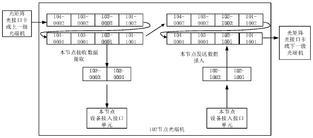
The invention belongs to the technical field of optical fiber communication, particularly relates to a multiplexed KVM optical transmission system, a cascaded optical transmitter and receiver and an optical interface card, and aims to solve the problem that a large number of optical fiber resources are occupied between an input / output node and a KVM switching controller in an existing KVM system.A KVM optical matrix multiplexes multiple paths of video data transmitted on an optical fiber link and sends the multiplexed video data to cascaded optical transceivers, and each cascaded optical transceiver extracts the video data of the node and / or inserts the control data of the node from a multiplexed data frame. The KVM optical matrix disassembles the received multi-path control data, multiplexes the control data through the corresponding optical interface card, sends the multiplexed control data to the corresponding cascaded optical transmitter and receiver, and receives a multiplexed data frame containing video data. According to the invention, multiple paths of data signals can be transmitted in a single path of optical signals, so that optical fiber resources are saved, and expansion of the port scale of the optical matrix is realized, and more node devices can be accessed under the condition of limited ports.

Description

technical field [0001] The invention belongs to the technical field of computer control equipment, and in particular relates to a multiplexed KVM optical transmission system, a cascade optical transceiver and an optical interface card. Background technique [0002] KVM stands for Keyboard, Video and Mouse, which is to use a set of keyboards, monitors and mice to control multiple devices. This technique has many advantages. First of all, in the management of the entire computer room, the traditional one-to-one control method has been changed, and a one-to-many management method has been adopted, which is conducive to saving space and improving work efficiency; secondly, the security performance of the host system has been greatly improved , and has long-distance transmission capabilities. In some large-scale system solutions, the KVM system with switch matrix function can satisfy end users' access to hundreds or even more servers at the same time. [0003] The main working...

Claims


Application Information

Patent Timeline
IPC IPC(8): H04N7/22H04Q11/00
CPCH04N7/22H04Q11/0003H04Q11/0067H04Q2011/0079
Inventor 刘雨姚维久李伟李厚鹏
Owner BEIJING DIGIBIRD TECH CO LTD
Learn More