
Antenna data packet transmission device and method

Antenna data and packetization technology, applied in the field of data transmission, can solve the problems of high fiber cost and wiring, limited number of connected RRUs, and large number of indirect fibers between BBU and RRU, so as to save wiring and cable costs and reduce construction layout Difficulty, the effect of optimizing the access method

Inactive Publication Date: 2018-07-03
ZTE CORP
View PDF6 Cites 5 Cited by
  • Summary
  • Abstract
  • Description
  • Claims
  • Application Information

AI Technical Summary

Problems solved by technology

[0008] The technical problem solved by the solution provided according to the embodiment of the present invention is that the BBU and the RRU cannot be interconnected due to inconsistent optical port rates, the BBU baseband processing resources cannot be fully utilized, the insufficient number of BBU optical ports leads to a limited number of connected RRUs, and the number of indirect fibers between the BBU and the RRU is large, The problem of high fiber cost and wiring, and the difficulty of accessing clock synchronization reference sources in scenarios such as ultra-long feeder wiring or feeder lines that cannot pass through walls for a long distance

Method used


Image

  • Antenna data packet transmission device and method
  • Antenna data packet transmission device and method
  • Antenna data packet transmission device and method

Examples


Embodiment Construction

[0040] The preferred embodiments of the present invention will be described in detail below in conjunction with the accompanying drawings. It should be understood that the preferred embodiments described below are only used to illustrate and explain the present invention, and are not intended to limit the present invention.

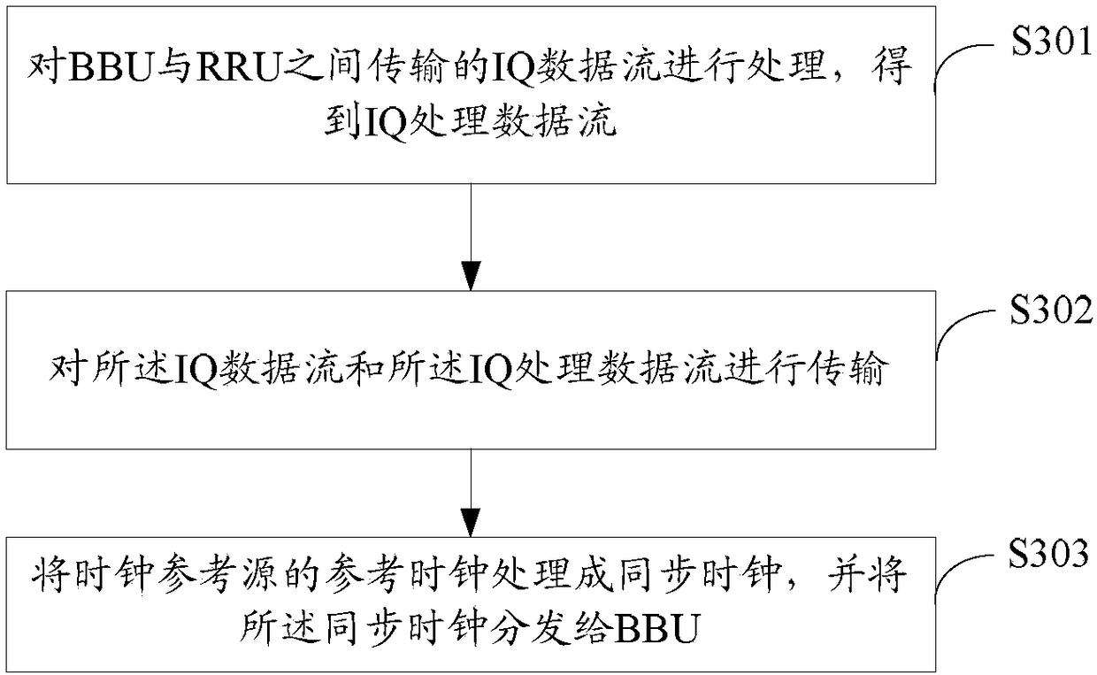
[0041] figure 2 It is a schematic diagram of a device for packetized antenna data transmission provided by an embodiment of the present invention, as shown in figure 2 As shown, it includes: an IQ antenna data exchange module 201, which is used to process the IQ data stream transmitted between the BBU and the RRU, to obtain an IQ processing data stream; an interface module 202, which is used to process the IQ data stream and the IQ data stream. Process the data stream for transmission; the clock module 203 is configured to process the reference clock of the clock reference source into a synchronous clock, and distribute the synchronous clock to the BBU....


PUM


Abstract

The invention discloses an antenna data packet transmission device and method. The device comprises an IQ antenna data exchange module used for carrying out processing on IQ data flow transmitted between a BBU and an RRU to obtain an IQ processed data flow; an interface module used for carrying out transmission on the IQ data flow and the IQ processed data flow; and a clock module used for processing a reference clock of a clock reference source into a synchronous clock, and distributing the synchronous clock to the BBU. The device can fully utilizes the processing capability of the BBU, expands the number of interfaces on the basis on limited number of interfaces at the RRU side, can connect more RRUs or conventional BBU devices, and meanwhile, can effectively save optical fiber resourcesbetween the BBU and the RRU, thereby reducing fiber cost, fiber layout difficulty and construction cost.

Description

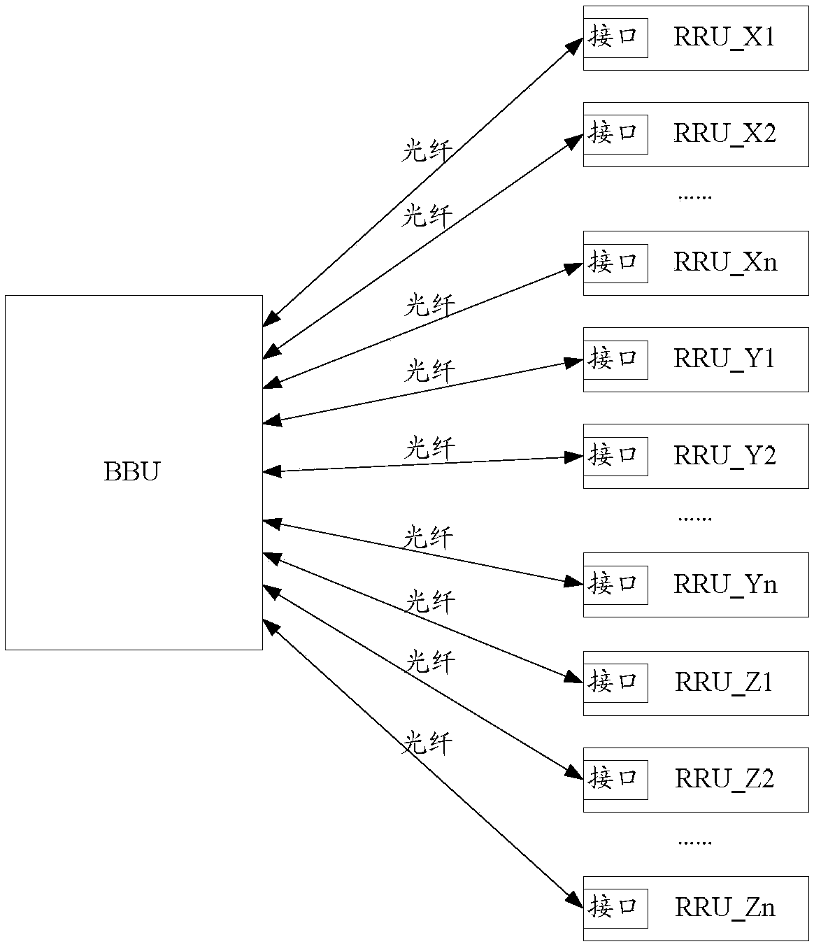
technical field [0001] The present invention relates to the technical field of data transmission, in particular to a device and method for antenna data packetized transmission. Background technique [0002] At present, a wireless distributed base station system is generally composed of a BBU (Base Band Unit, base band unit) and an RRU (Remote Radio Unit, radio frequency remote unit). Among them, BBU is responsible for baseband processing and communication interaction with upper-layer network devices; RRU is responsible for uplink and downlink RF signal processing and UE (User Equipment, user equipment) interaction functions. Currently, BBU and RRU are directly connected by optical fiber, and the interface adopts CPRI (Common Public Radio Interface, common public radio interface), such as figure 1 shown. [0003] With the rapid development of 5G technology, the processing capacity of 5G base stations must reach 1,000 times that of 4G, and the massive MIMO (Multiple-Input Mu...

Claims


Application Information

Patent Timeline
IPC IPC(8): H04W56/00H04W88/08H04J3/06
CPCH04J3/0658H04W56/001H04W88/085
Inventor 李杨于海丹段向阳封葳付玉堂
Owner ZTE CORP
Learn More