Hybrid passive optical network transmitting/receiving device

A technology of passive optical network, transceiver device, applied in the direction of selection device, selection device of multiplexing system, transmission system, etc., can solve the problems of high network cost and influence, save fiber resources, reduce cost, expand network-wide effects

Active Publication Date: 2011-09-28
SHANGHAI BROADBAND TECH
View PDF0 Cites 0 Cited by
  • Summary
  • Abstract
  • Description
  • Claims
  • Application Information

AI Technical Summary

Problems solved by technology

If the optical fiber is re-laid, the cost of the entire network will be very expensive, and it will also affect the existing network

Method used


Image

  • Hybrid passive optical network transmitting/receiving device
  • Hybrid passive optical network transmitting/receiving device

Examples


Embodiment Construction

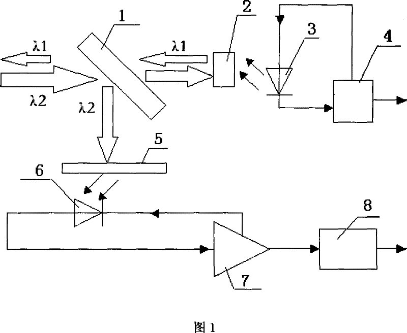
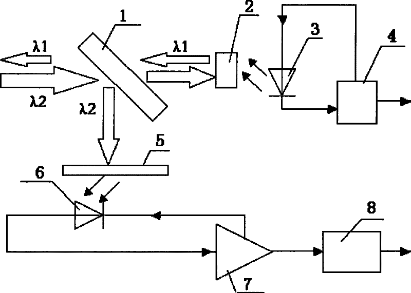
[0031] Such as figure 1 As shown, a hybrid passive optical network transceiver, including:

[0032] The optical splitter 1 is used for optical path coupling, and is used to couple the uplink optical signal λ1 sent by the laser and the downlink optical signal λ2 received by the receiver into one optical fiber; the optical splitter 1 can use a 50% / 50% optical splitter;

[0033] The isolator 2, which conducts in one direction, allows the uplink optical signal λ1 sent by the laser to pass through, and blocks the downlink optical signal λ2 from entering the laser; it is used to protect the laser and prevent the laser from being impacted by external optical signals; the isolator 2 can use polarization correlation the isolator.

[0034] The laser 3 is used to send out an uplink optical signal conforming to the coarse wavelength division multiplexing standard, that is, the center wavelength is from 1400nm to 1600nm, and the channel spacing is 20mm. The laser 3 in this embodiment can...


PUM


Abstract

The invention relates to a mixed type passive optical network transmitting and receiving device which comprises an optical splitter, a laser, a modulating chip, a coarse wavelength division multiplexing filter and a photoelectric receiving tube, wherein, the optical splitter is used for coupling uplink optical signals and downlink optical signals; the laser is used for sending out uplink optical signals which accord with coarse wavelength division multiplexing standards; the modulating chip is connected with the laser and used for driving the laser and modulating information needed for transmission to optical signals; the coarse wavelength division multiplexing filter is used for filtering downlink optical signals which are inputted by the optical splitter, and center-wavelength downlink optical signals which accord with the wavelength division multiplexing standards are made to pass and other optical signals are filtered; the photoelectric receiving tube is used for converting downlink optical signals passing by the coarse wavelength division multiplexing filter into electrical signals. The invention adopts CWDM Standard and simultaneously also accords with EPON Transmission Standard, thereby the device can be well used in a mixed type network of EPON and CWDM.

Description

technical field [0001] The invention relates to a passive optical network system, in particular to a passive optical network transceiver. Background technique [0002] The passive optical network (PON) provides the connection between the optical line terminal (OLT) and multiple optical network units (ONU), and shares the optical fiber medium between the OLT and the remote node (RN). It has advantages such as business transparency, and at the same time, PON can smoothly transition to fiber-to-the-home (FTTH), so it has a good development prospect. [0003] Existing ONUs are mainly Fabry-Perot FP lasers, whose uplink working wavelength is 1310nm, and downlink working wavelength is 1490nm. However, the working wavelength of the current wired network is mainly 1310nm. If the PON network is directly used to transform the cable TV network, there will be compatibility problems, which will cause the original business to fail. The existing wired network has insufficient optical fib...

Claims


Application Information

Patent Timeline
Patent Type & Authority Patents(China)
IPC IPC(8): H04B10/02H04J14/02H04J3/08H04Q11/00
Inventor 刘浩峰
Owner SHANGHAI BROADBAND TECH
Why Eureka
Try Eureka