
Hybrid Passive Optical Network System

A passive optical network, hybrid technology, applied in the direction of wavelength division multiplexing system, etc., can solve the problems of expensive network cost, affecting the development of EPON, network impact, etc., to expand the network range, facilitate network performance maintenance and management, reduce troublesome effect

Active Publication Date: 2012-02-01
SHANGHAI BROADBAND TECH
View PDF0 Cites 0 Cited by
  • Summary
  • Abstract
  • Description
  • Claims
  • Application Information

AI Technical Summary

Problems solved by technology

Although it can save a lot of optical fiber resources compared with traditional transmission methods, the development of EPON is still seriously affected due to the lack of original optical fiber resources in China.
If the optical fiber is re-laid, this will lead to a very expensive cost of the entire network, and at the same time have a serious impact on the existing network

Method used


Image

  • Hybrid Passive Optical Network System
  • Hybrid Passive Optical Network System

Examples


Embodiment Construction

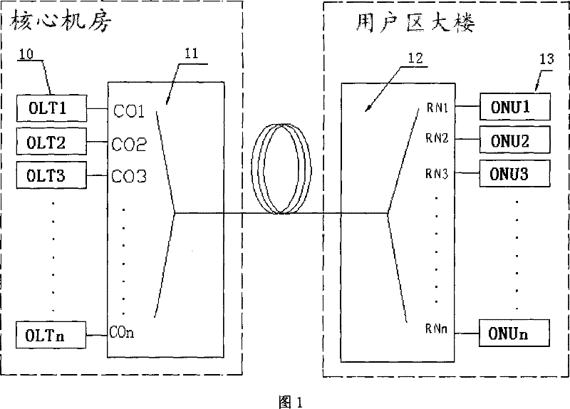
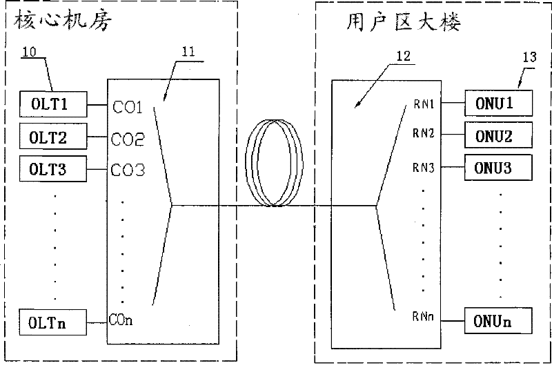
[0024] Such as figure 1 As shown, a hybrid passive optical network system includes:

[0025] A plurality of optical line terminals (OLT) 10 of the Ethernet optical network, that is, OLT1, OLT2, OLT3, ..., OLTn in the figure, each optical line terminal 10 occupies two different wavelengths of the coarse wavelength division multiplexing (CWDM) standard . For example, OLT1 is respectively λ1, λ1', OLT2 is respectively λ2, λ2'; OLT3 is respectively λ3, λ3'; ...; OLTn is respectively λn, λn'. They are respectively used for the transmission of optical signals at the OLT transmitter and receiver. Among them, the transmitting end of the OLT can use a distributed feedback Bragg grating (DFB) laser, and each OLT is stored side by side in the core computer room.

[0026] Coarse wavelength division multiplexing and demultiplexing device 11, used for optical signals of different wavelengths (λ1, λ1', λ2, λ2', λ3, λ3', ..., λn, λn') of the multiple OLTs in Transmission is performed on t...


PUM


Abstract

A hybrid passive optical network system includes: a plurality of optical line terminals, each optical line terminal occupies two different wavelengths of the coarse wavelength division multiplexing standard; transmission; coarse wavelength division multiplexing and demultiplexing devices; optical splitters provided with multiple ports, connected with the coarse wavelength division multiplexing and demultiplexing devices through optical fibers; a plurality of optical network units, and optical branching The corresponding port optical communication connection of the device. The present invention adopts mature coarse wavelength division technology to simultaneously superimpose a plurality of mutually independent EPON systems into a single optical fiber through different CWDM optical wavelengths. At the same time, it is shared to each ONU through the optical splitter. This topology greatly saves the optical fiber resources connected between the metropolitan area network and the cell, and further exerts the advantages of EPON, which can flexibly increase the number of users, reduce the cost of each line, and accelerate the promotion of EPON networks.

Description

technical field [0001] The present invention relates to Passive Optical Network (PON) systems. Background technique [0002] The passive optical network (PON) provides the connection between the optical line terminal (OLT) and multiple optical network units (ONU), and shares the optical fiber medium between the OLT and the remote node (RN). This service has the advantages of transparency, etc., and at the same time, PON can smoothly transition to fiber-to-the-home (FTTH), so it has a bright development prospect. [0003] Ethernet Passive Optical Network (EPON) is a power-splitting passive optical network, which adopts star coupler for branching, and uplink / downlink transmission adopts time division multiple access (TDMA) / time division multiplexing (TDM) to realize shared channel bandwidth. It uses optical power distribution, which limits the number of ONUs and affects further network expansion. [0004] One OLT can be installed on each optical fiber of the traditional EPON...

Claims


Application Information

Patent Timeline
Patent Type & Authority Patents(China)
IPC IPC(8): H04J14/02
Inventor 刘浩峰
Owner SHANGHAI BROADBAND TECH
Learn More