

Time synchronization signal and frequency synchronization signal providing method and apparatus
A time synchronization and signal technology, which is applied in the direction of synchronization devices, wireless communications, electrical components, etc., can solve problems such as base station slippage and failure to work normally, and achieve the effects of improving security, speeding up deployment, and reducing investment
- Summary
- Abstract
- Description
- Claims
- Application Information
AI Technical Summary
Problems solved by technology
Method used
Image

Examples
Embodiment 1
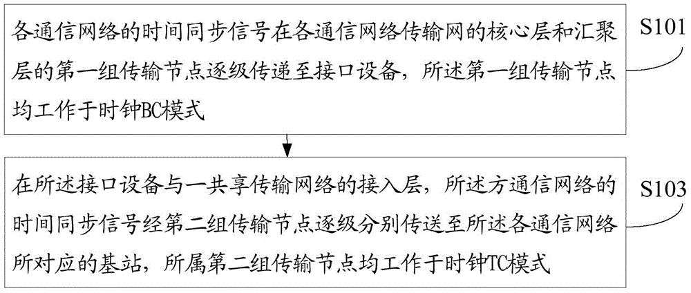
[0043] figure 1 A main flowchart showing the method for providing a time synchronization signal according to Embodiment 1 of the present invention.
[0044] see figure 1 As shown, the methods for providing time synchronization signals include:
[0045] S101: The time synchronization signal of each communication network is transmitted to the interface device step by step at the core layer and the first group of transmission nodes of the convergence layer of the transmission network of each communication network, wherein the first group of transmission nodes all work in the clock BC mode;
[0046] S103: At the access layer of the interface device and a shared transmission network, the time synchronization signals of the communication networks are respectively transmitted to base stations corresponding to the communication networks step by step through the second group of transmission nodes, wherein the The second group of transmission nodes all work in the clock TC mode.
[004...
Embodiment 2
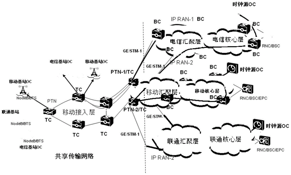
[0054] figure 2 A specific flow chart showing the method for providing a time synchronization signal according to Embodiment 2 of the present invention.
[0055] For details, see figure 2 As shown, usually, the clock path nodes of the transmission network all work in the clock BC mode, figure 2 In the core layer of the transmission network, the transmission nodes of the aggregation layer all work in the clock BC mode, and the time signal obtained from the clock source is passed down step by step to the packet transport network equipment PTN-1 / PTN-2, PTN-1 / PTN -2 and below shared transmission network (access layer equipment) all work in clock TC mode.
[0056] The reason for this design is that when the transmission device works in the clock BC mode, the clock node parses the 1588v2 message from the upstream signal, recovers the time signal and continues to transmit it downstream, and the BC mode can only track the upstream clock Signal, assuming that PTN-1 / PTN-2 is track...
Embodiment 3
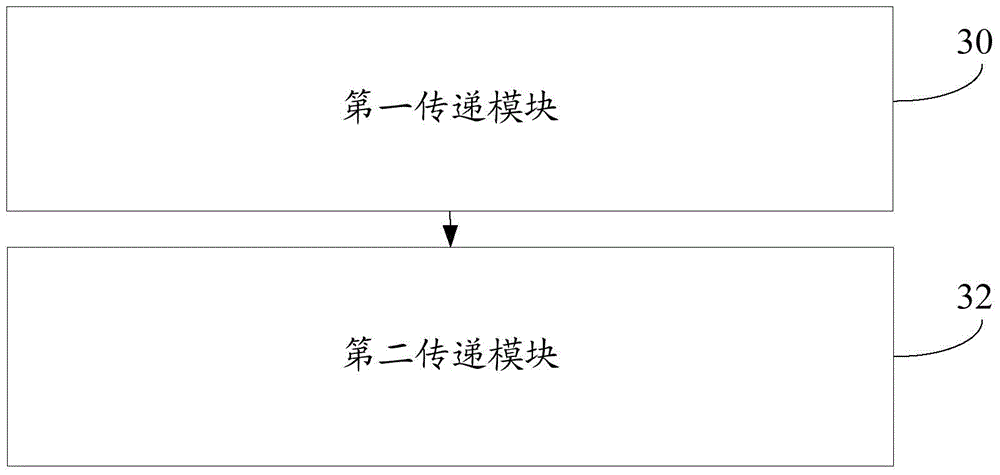
[0058] image 3 A schematic structural diagram of the device for providing a time synchronization signal according to Embodiment 3 of the present invention is shown.
[0059] see image 3 As shown, the device for providing time synchronization signals includes: a first transmission module 30, which is used to transmit the time synchronization signals of each communication network down to the interface step by step at the core layer of each communication network transmission network and the first group of transmission nodes at the convergence layer equipment, wherein the first group of transmission nodes all work in the clock BC mode; the second transmission module 32 is used to connect the interface equipment and a shared transmission network access layer, and the time synchronization signals of each communication network pass through the first The two groups of transmission nodes respectively transmit to the base stations corresponding to the respective communication network...
PUM
 Abstract
Description
Claims
Application Information