
Suspension type self-balancing hydraulic lifting device

A technology of hydraulic lifting device and lifting device, applied in welding equipment, laser welding equipment, metal processing equipment and other directions, can solve the problems of high cost, stop overshoot, stuck, etc., achieve high bearing load, ensure normal work, reduce The effect of friction

Pending Publication Date: 2019-11-05
FOSHAN HONGSHI LASER TECH CO LTD
View PDF8 Cites 5 Cited by
  • Summary
  • Abstract
  • Description
  • Claims
  • Application Information

AI Technical Summary

Problems solved by technology

[0002] Now, in plane laser cutting, with the increase of the power of the laser cutting machine, the increase of the thickness of the cutting plate and the increase of the cutting format, the disadvantages of the original exchange table driven by the motor reducer to drive the gear cam structure are getting more and more Large, the main problems are high cost, overshoot when stopping, and inaccurate stopping
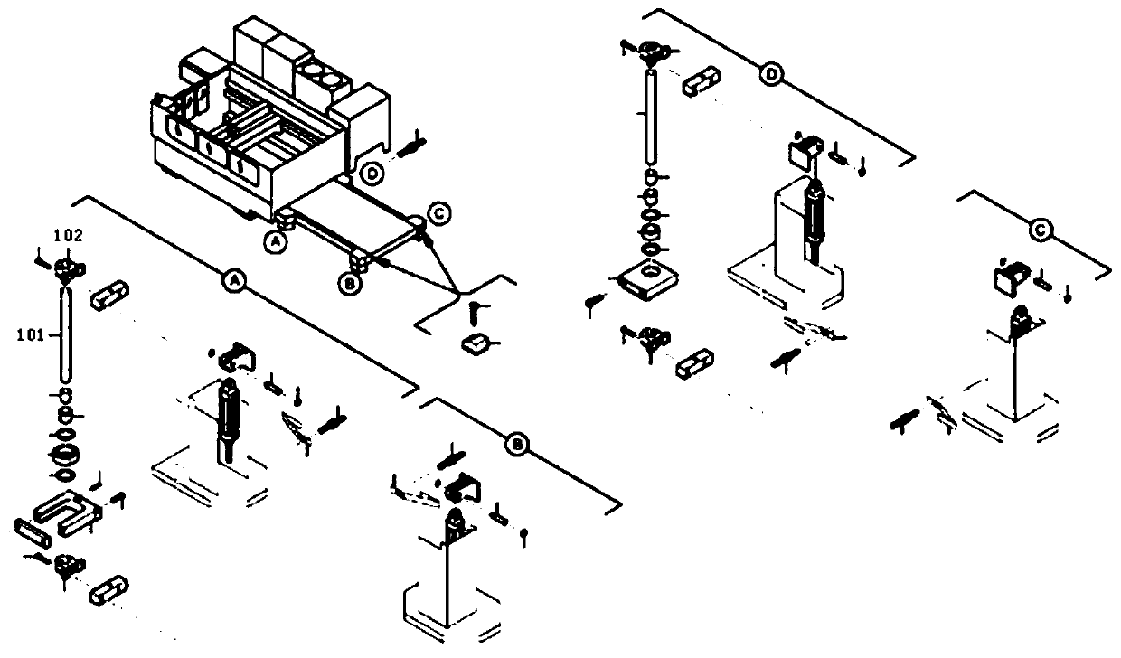
[0003] refer to figure 1 , the current domestic hydraulic lifting platform has four hydraulic cylinders for lifting, and four guide columns 101 are used for guidance. The hydraulic cylinders are connected to the guide ring 102, and the guide ring 102 is inserted into the guide column 101. Each guide post 101 must be perpendicular to the horizontal plane, which increases the cost and makes installation difficult. If the hydraulic cylinder is out of sync, it will be stuck

Method used


Image

  • Suspension type self-balancing hydraulic lifting device
  • Suspension type self-balancing hydraulic lifting device
  • Suspension type self-balancing hydraulic lifting device

Examples


Embodiment Construction

[0033] In order to make the object, technical solution and advantages of the present invention more clear, the present invention will be further described in detail below in conjunction with the examples, but the protection scope of the present invention is not limited to the following specific examples.

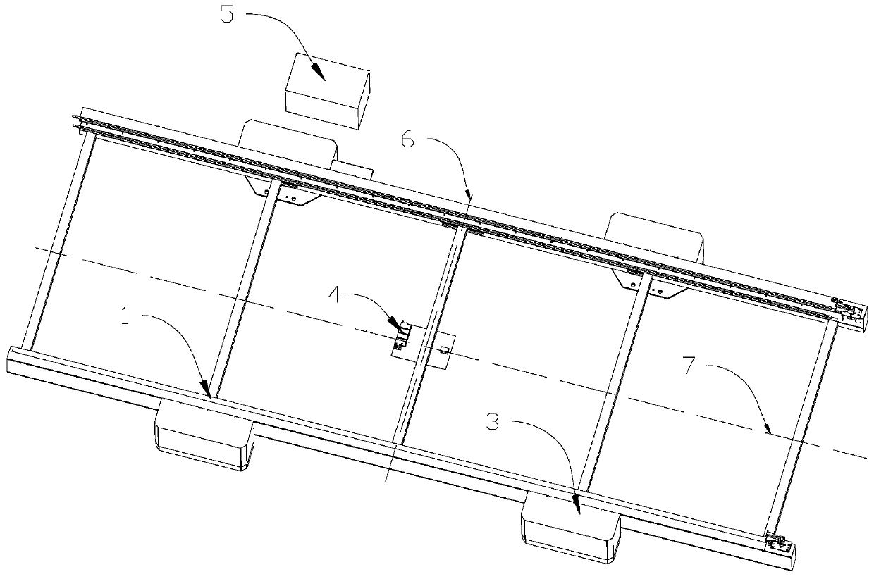
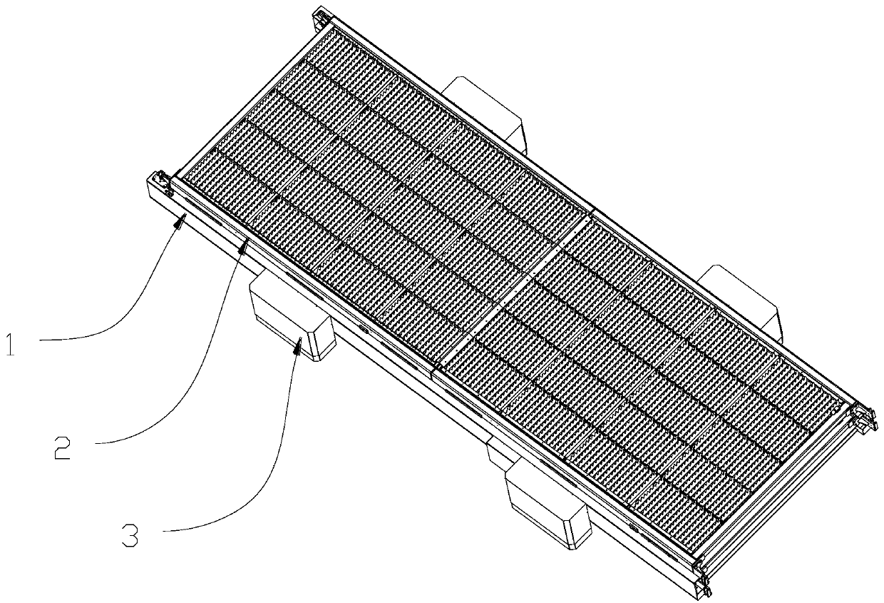
[0034] refer to Figure 2-8 , this embodiment discloses a suspended self-balancing hydraulic lifting device, including a rectangular support 1, a synchronous motor 4, four lifting devices and a hydraulic station 5; the center of the support 1 extends along the length direction and extends along the width direction Respectively form X-axis 7 and Y-axis 6, four lifting devices are located on opposite sides of support 1, each side of the opposite sides of support 1 is provided with two lifting devices, and the lifting devices on opposite sides are arranged with X-axis 7 It is set symmetrically to the center line, and the two lifting devices on the same side are set symmetricall...


PUM


Abstract

The invention discloses a suspension type self-balancing hydraulic lifting device which comprises a bracket, a synchronous motor, lifting devices and a hydraulic station; the center of the bracket extends in a length direction and extends in a width direction to form an X axis and a Y axis respectively; and the four lifting devices are symmetrically arranged in the X axis and the Y axis; each lifting device comprises a hydraulic cylinder, a supporting block and a positioning block; a supporting block is connected to a moving rod of each hydraulic cylinder; the positioning blocks and the supporting blocks are arranged on the lower surface of the bracket in a one-to-one correspondence manner; the positioning blocks is separably tangent and abutted to the surfaces of the corresponding supporting blocks; and the synchronous motor is arranged at an intersection of the X axis and the Y axis. The lifting device disclosed by the invention does not have the deadlocking phenomenon in the liftingprocess; the perpendicularity of the lifting device is not strictly required, and the production cost is low; by adopting hydraulic power, the bearing load is high, lifting is stable, and a stop position is accurate; and the overall structure is stable.

Description

technical field [0001] The invention relates to the field of lifting devices for working platforms, in particular to a suspended self-balancing hydraulic lifting device. Background technique [0002] Now, in plane laser cutting, with the increase of the power of the laser cutting machine, the increase of the thickness of the cutting plate and the increase of the cutting format, the disadvantages of the original exchange table driven by the motor reducer to drive the gear cam structure are getting more and more Large, the main problems are high cost, overshoot when stopping, and inaccurate stopping. [0003] refer to figure 1 , the current domestic hydraulic lifting platform has four hydraulic cylinders for lifting, and four guide columns 101 are used for guidance. The hydraulic cylinders are connected to the guide ring 102, and the guide ring 102 is inserted into the guide column 101. Each guide post 101 must be perpendicular to the horizontal plane, which increases the co...

Claims


Application Information

Patent Timeline
IPC IPC(8): B23K26/38B23K26/70
CPCB23K26/38B23K26/702
Inventor 常勇
Owner FOSHAN HONGSHI LASER TECH CO LTD
Learn More