Working table for stone machining

A stone processing and workbench technology, applied in stone processing equipment, work accessories, manufacturing tools, etc., can solve the problems of inconvenient rotation, difficulty in adjusting the inclination angle of stone, inconvenience, etc., to save workers' time, facilitate processing operations, and improve efficiency high effect

Inactive Publication Date: 2019-11-05
刘志成
View PDF8 Cites 12 Cited by
  • Summary
  • Abstract
  • Description
  • Claims
  • Application Information

AI Technical Summary

Problems solved by technology

[0003] When stone is processed, it is often necessary to rotate the stone or tilt the stone at a certain angle to facilitate the processing operation. After the existing s

Method used


Image

  • Working table for stone machining
  • Working table for stone machining
  • Working table for stone machining

Examples


Embodiment 1

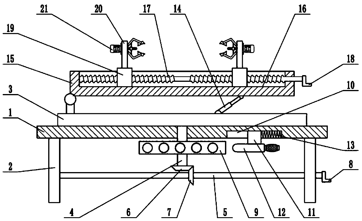
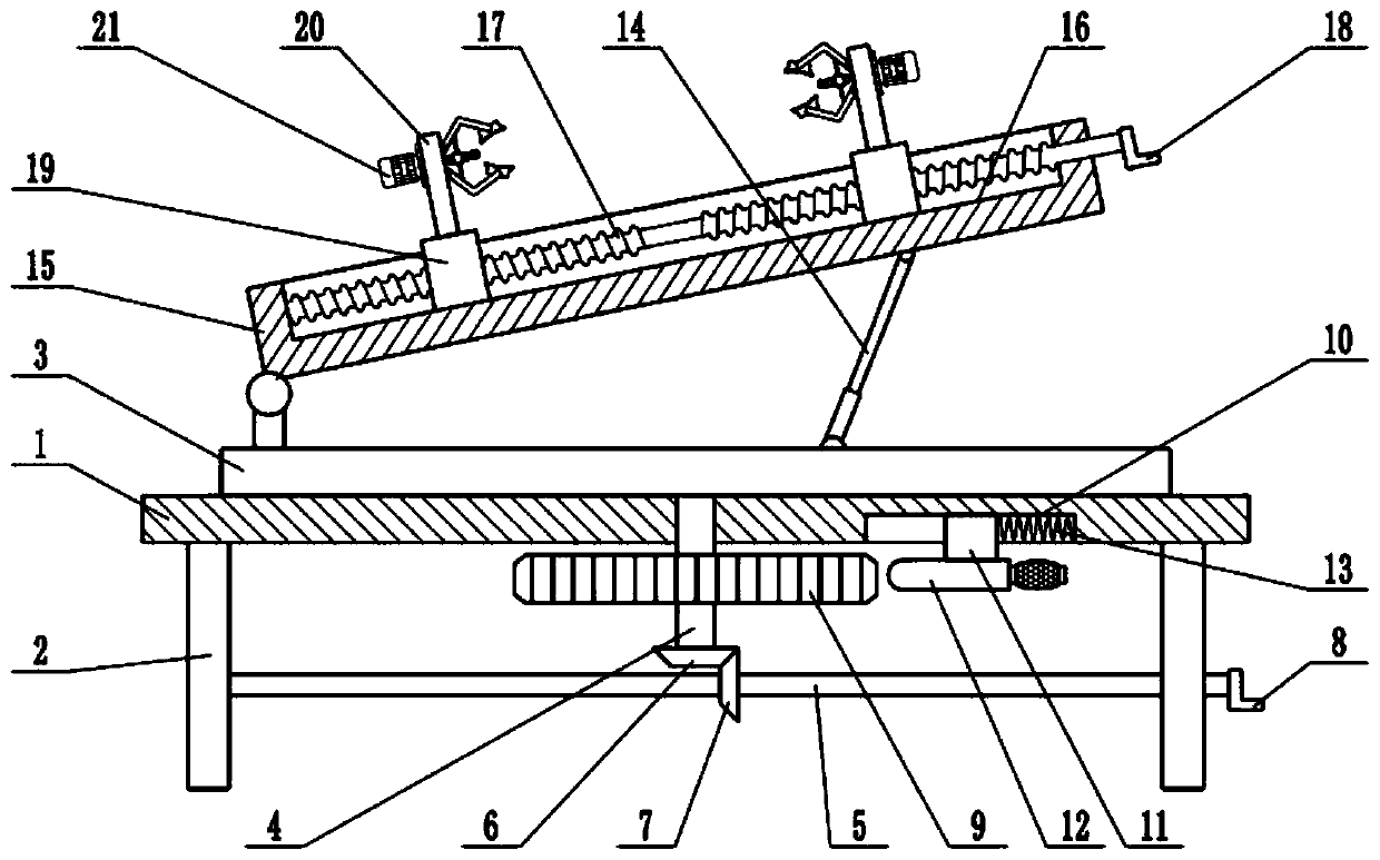
[0021] see Figure 1-4 , in an embodiment of the present invention, a workbench for stone processing includes a table top 1, a movable plate 15, a clamping block 19 and a clamping plate 20, the lower surface of the table top 1 is fixedly connected with a support plate 2, and the bottom surface of the table top 1 The upper surface is rotatably connected with a rotary table 3, and the lower surface of the rotary table 3 is fixedly connected with a rotating shaft 4. The lower end of the rotating shaft 4 passes through the table top 1 and extends to the bottom of the table top 1. The rotating shaft 4 is connected to the table top 1 in rotation. The transmission shaft 5, the two ends of the transmission shaft 5 are respectively connected to the support plate 2 in rotation, the end of the transmission shaft 5 is equipped with a first handle 8, the middle part of the transmission shaft 5 is provided with a second bevel gear 7, and the lower end of the rotation shaft 4 The first bevel...

Embodiment 2

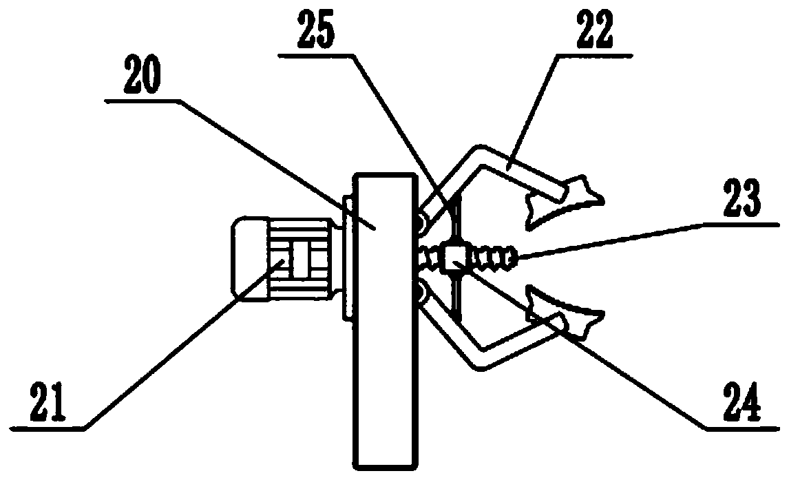
[0023] On the basis of Embodiment 1, a clamping plate 20 is fixedly connected to the upper surface of the clamping block 19, and a clamping mechanism is installed on the clamping plate 20. The clamping mechanism includes a clamping motor 21, clamping jaws 22, clamping wire Rod 23, slide block 24 and clamping link 25, one side of clamping plate 20 is fixedly connected with clamping motor 21, and the shaft extension end of clamping motor 21 is fixedly connected with clamping screw rod 23, and clamping plate 20 The other side is hinged with jaws 22. There are two jaws 22 arranged symmetrically up and down. A clamping link 25 is hinged, and the end of the clamping link 25 is hinged with the slide block 24. The clamping motor 21 is a positive and negative motor, and the positive and negative rotation of the control clamping motor 21 can drive the clamping screw mandrel 23 to rotate. Thereby, the slide block 24 is driven to move laterally, and the jaws 22 are driven to open or close...


PUM


Abstract

The invention relates to the field of stone machining equipment, and more particularly relates to a working table for stone machining. The working table comprises a table top, a movable plate, clamping blocks and clamping plates, wherein the lower surface of the table top is fixedly connected to supporting plates; the upper surface of the table top is rotatably connected to a rotary table; the lower surface of the rotary table is fixedly connected to a rotating shaft; a transmission shaft is arranged below the rotating shaft; a positioning plate is arranged on the rotating shaft in a sleevingmanner; the movable plate is arranged above the rotary table; a sliding chute is formed in the upper surface of the movable plate; a bidirectional lead screw is arranged inside the sliding chute; theclamping blocks are arranged on the bidirectional lead screw in a sleeving manner; the upper surfaces of the clamping blocks are fixedly connected to the clamping plates; clamping mechanisms are arranged on the clamping plates; stone to be machined is put between the two clamping plates; the two ends of the stone are clamped by using the clamping mechanisms, so that the stone is fixed, the clamping speed is fast, and the efficiency is high; the inclination of the stone can be adjusted in the machining process according to the actual machining requirements, and meanwhile the rotary table can beconveniently rotated so as to adjust the machining position of the stone.

Description

technical field [0001] The invention relates to the field of stone processing equipment, more specifically, a workbench for stone processing. Background technique [0002] As a high-grade building decoration material, stone is widely used in indoor and outdoor decoration design, curtain wall decoration and public facilities construction. At present, the common stone materials on the market are mainly divided into natural stone, artificial stone and marble. [0003] When stone is processed, it is often necessary to rotate the stone or tilt the stone at a certain angle to facilitate the processing. The existing stone processing workbench is inconvenient to rotate after the clamping is completed, and it is difficult to adjust the inclination angle of the stone, which is very difficult. inconvenient. Contents of the invention [0004] The purpose of the present invention is to provide a workbench for stone processing, so as to solve the problems raised in the above-mentioned...

Claims


Application Information

Patent Timeline
IPC IPC(8): B28D7/04B24B41/06
CPCB24B41/06B28D7/04
Inventor 刘志成
Owner 刘志成
Why Eureka
Try Eureka