Method and a system for detecting rod pumped well polish rod suspension center dead point

A technology for pumping wells and detection methods, which is applied in the direction of measurement, drill pipe, drilling equipment, etc., can solve problems such as dead point drift, accuracy cannot be guaranteed, and affect displacement detection accuracy, so as to achieve high safety, improve monitoring capabilities, and maintain convenient effect

Active Publication Date: 2019-11-05
CHINA PETROLEUM & CHEM CORP +1
View PDF10 Cites 3 Cited by
  • Summary
  • Abstract
  • Description
  • Claims
  • Application Information

AI Technical Summary

Problems solved by technology

For the displacement detection method, the most commonly used method is to measure the position indirectly by measuring the acceleration, which can realize the wireless test of the displacement, simplify the test procedure, improve the reliability of the dynamometer measuring instrument and the accuracy of the displacement test data, However, there is a problem in the acceleration sensor measuring the displacement that the dead point drifts due to the acceleration oscillation of the dead point, which affects the displacement detection accuracy; for the dead point switch method, the dead point switch installed at the suspension point is easily damaged by collision
In summary, the current dead point detection method for the suspension point of pumping wells has problems such as high investment and maintenance costs, poor implementability, and unguaranteed accuracy.

Method used


Image

  • Method and a system for detecting rod pumped well polish rod suspension center dead point
  • Method and a system for detecting rod pumped well polish rod suspension center dead point
  • Method and a system for detecting rod pumped well polish rod suspension center dead point

Examples


Embodiment 1

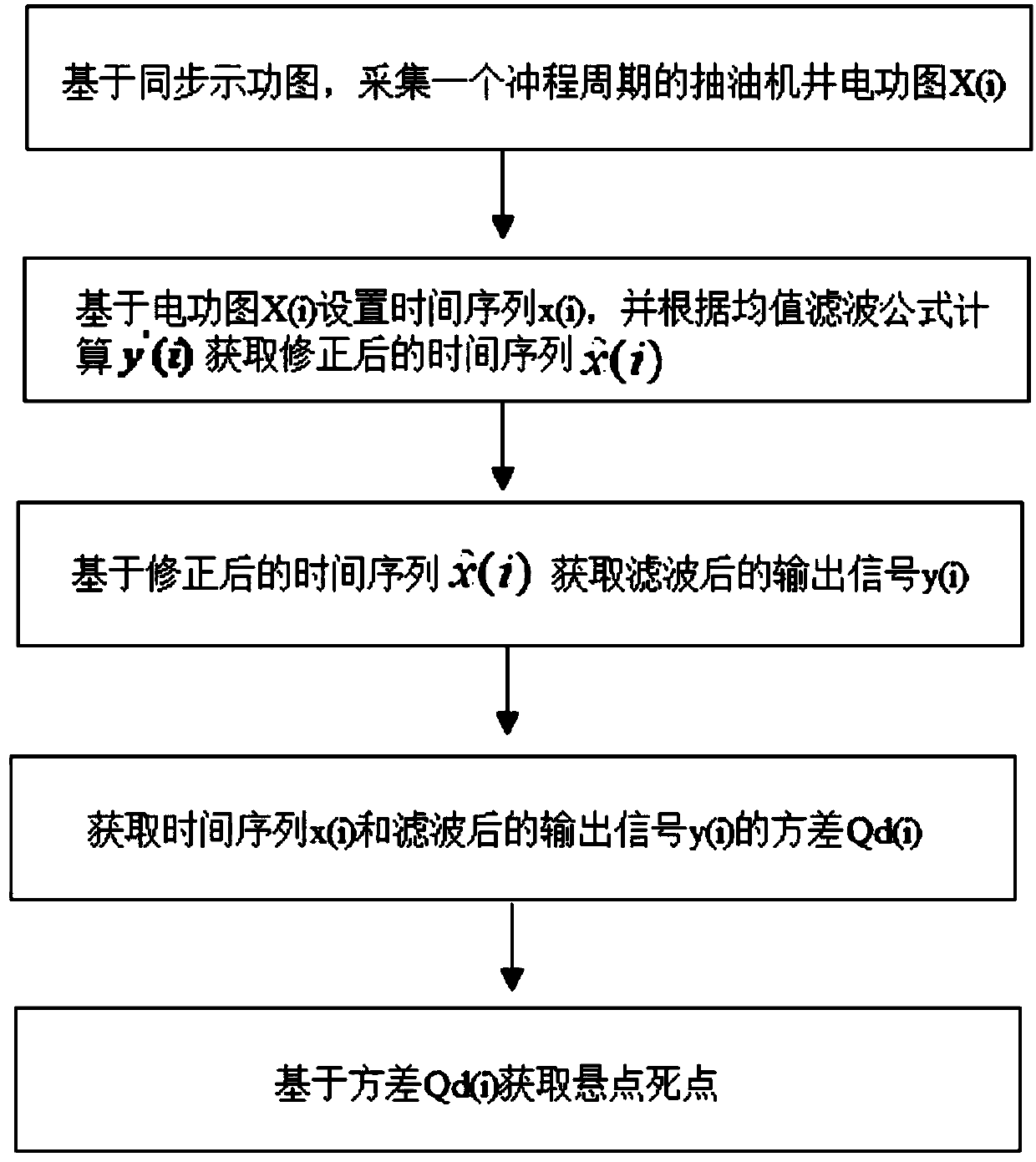
[0098] figure 1 A flow chart showing the steps of a method for detecting the dead center of a polished rod of a pumping unit according to an exemplary embodiment of the present invention.

[0099] like figure 1 As shown, the present embodiment provides a detection method for the dead point of the polished rod of the pumping unit, including:

[0100] Based on the synchronous dynamometer diagram, collect the electric power diagram X(i) of the pumping well for one stroke cycle;

[0101] Set the time series x(i) based on the electric power diagram X(i), and calculate y'(i) according to the mean filter formula to obtain the corrected time series

[0102] Based on the corrected time series Obtain the filtered output signal y(i);

[0103] Obtain the variance Qd(i) of the time series x(i) and the filtered output signal y(i);

[0104] Obtain the dead point of the suspension point based on the variance Qd(i).

[0105] Among them, the variance Qd(i) is:

[0106]

[0107] Fur...

Embodiment 2

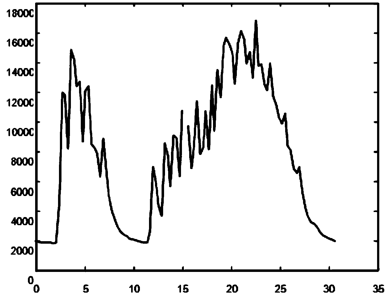
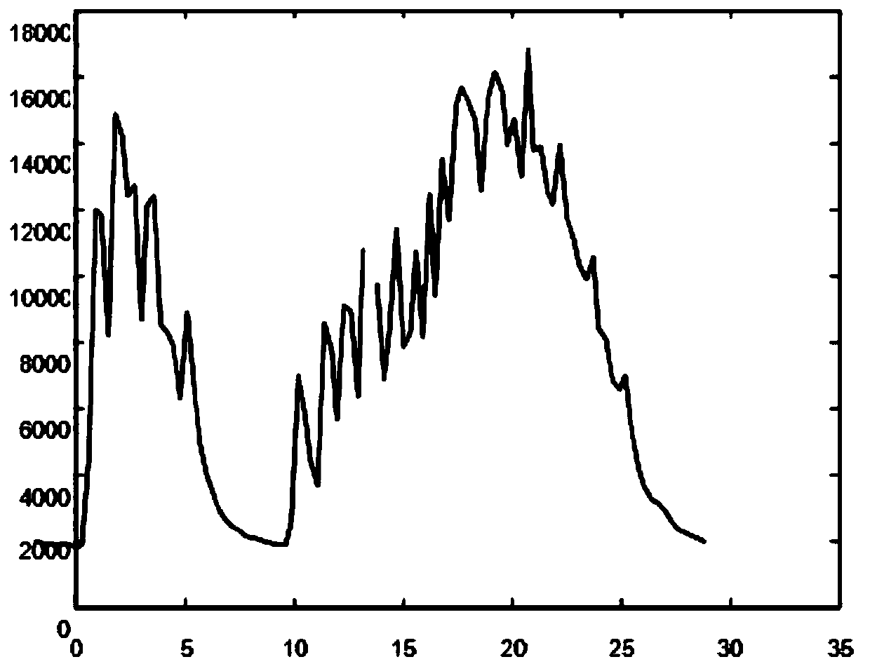
[0133] figure 2 It shows a periodic electric power diagram output synchronously with the indicator diagram of a pumping unit well according to an exemplary embodiment of the present invention. image 3 It shows a corrected cycle electric power diagram according to an exemplary embodiment of the present invention.

[0134] like figure 2 and image 3 As shown, the method of Example 1 is applied to the well number X109X102, and it can be seen that based on the synchronous dynamometer diagram acquisition of the pumping unit well cycle electric power diagram, the method detects that the electric power diagram collected by the well has a dead point lag, figure 2 The calculated liquid volume of the collection graph will lead to an increase in the judgment of the effective stroke, which will lead to a larger calculated liquid volume. The corrected electric power diagram is as follows: image 3 As shown, the obtained corrected cycle electric power diagram realizes the purpose of...


PUM


Abstract

The invention discloses a method and system for detecting a rod pumped well polish rod suspension center dead point. The detecting method comprises the steps that a rod pumped well electric work diagram X(i) in one stroke period is collected based on a synchronous indicator diagram; a time series x(i) is set based on the electric work diagram X(i), y'(i) is calculated according to a mean filteringformula, a corrected time series is obtained, and a filtered output signal y(i) is obtained based on the corrected time series; a variance Qd(i) of the time series x(i) and the filtered output signaly(i) is obtained; and the suspension center dead point is obtained based on the variance Qd(i). The method and system have the advantages that online correction of the electric work diagram and the indicator diagram of a rod pumped well can be achieved, real-time detection of the suspension center dead point is helpful for judging whether a displacement sensor of the indicator diagram is normal or not, the monitoring capability of the rod pumped well working condition is improved, and the method is high in safety and convenient in actual application installation, operation and maintenance.

Description

technical field [0001] The invention relates to the field of oil pumping well working condition monitoring and liquid volume measurement, and more particularly relates to a method and system for detecting the dead point of the polished rod of the pumping well. Background technique [0002] In order to improve the production efficiency and management level of oil and gas production enterprises, oil wells in various oil fields generally use dynamometer diagrams to measure oil well fluid volume online and monitor oil well working conditions. The dynamometer monitoring diagnostic measurement system consists of three parts: perception layer, transmission layer and application layer. Data such as pumping well indicator map and well start and stop information are collected through on-site sensor equipment, and the data is transmitted to the data processing unit RTU. The RTU transmits the data to the server through a wireless or wired network, and the server calculates and processes...

Claims


Application Information

Patent Timeline
Patent Type & Authority Applications(China)
IPC IPC(8): E21B47/00E21B17/00E21B43/00
CPCE21B47/00E21B17/00E21B43/00
Inventor 王军霞黄辉姜家厅王晓港刘德生
Owner CHINA PETROLEUM & CHEM CORP
Why Eureka
Try Eureka