Labyrinth bidirectional catalytic combustion heater
A catalytic combustion and heater technology, used in burners, water heaters, fluid heaters, etc., can solve the problems that the heating speed of fuel heaters cannot meet the needs of customers, cannot be uniformly catalyzed, and cannot be fully burned, and achieve heating Fast speed, full burn, full burn effect
- Summary
- Abstract
- Description
- Claims
- Application Information
AI Technical Summary
Problems solved by technology
Method used
Image
Examples
Embodiment 1
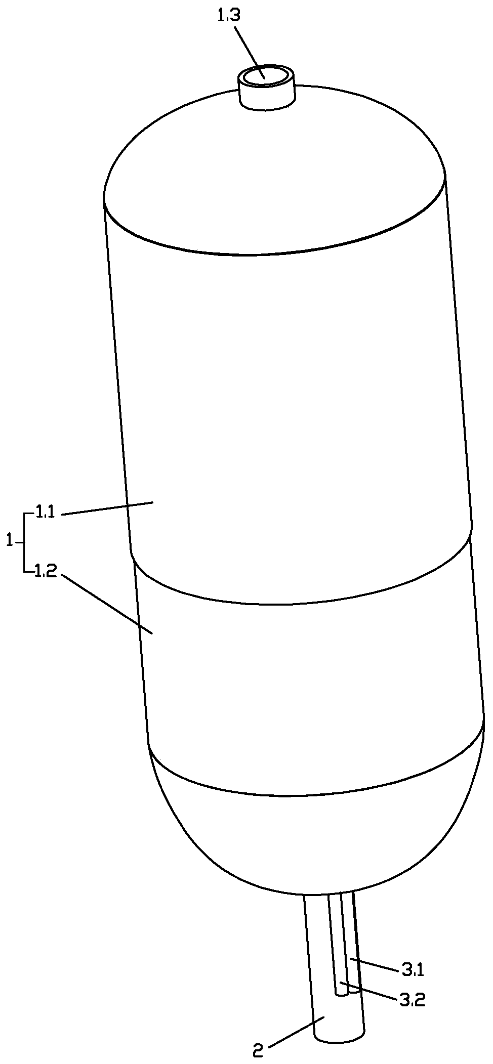
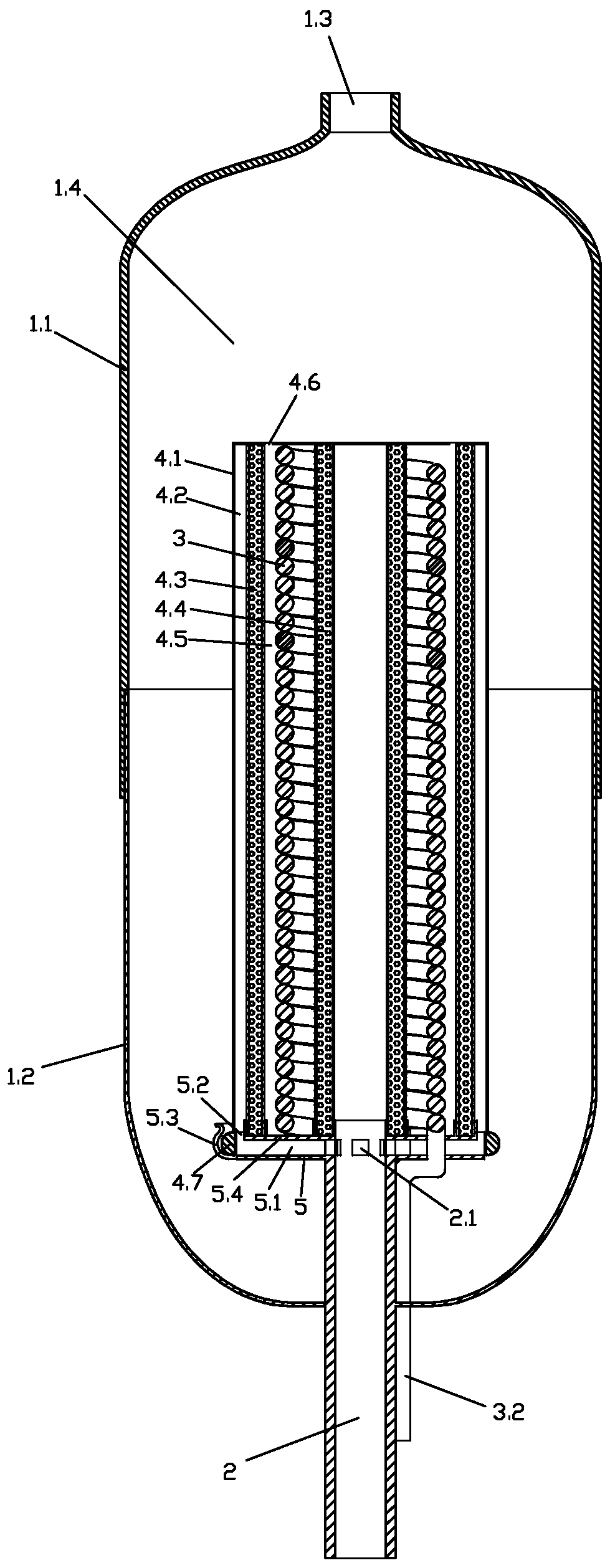
[0047] Such as Figure 1 to Figure 8 Shown is the labyrinth type two-way catalytic combustion heater of Embodiment 1, which includes an outer casing 1, an air intake pipe 2, a heat exchange device 3 and a heating inner core 4, wherein the heating inner core 4 includes an inner casing 4.1 for The first combustion-supporting catalytic body 4.3 and the second catalytic body 4.4 that the gas plays a combustion-supporting or catalytic role.
[0048] The outer casing 1 is cylindrical, with a gas buffer cavity 1.4 inside, and an exhaust port 1.3 communicating with the gas buffer cavity 1.4 at the upper end. The outer casing 1 includes an upper casing 1.1 and a lower casing 1.2, and the upper casing 1.1 and the lower casing 1.2 are connected by a threaded seal, and the internal parts of the labyrinth bidirectional catalytic combustion heater can be maintained by disassembling the upper casing 1.1 .
[0049] The air intake pipe 2 penetrates into the gas buffer chamber 1.4 from the lo...
Embodiment 2
[0061] The difference between the labyrinth bidirectional catalytic combustion heater of the second embodiment and the labyrinth bidirectional catalytic combustion heater of the first embodiment lies in the heat exchange device 3 .
[0062] Such as Figure 9 As shown, the heat exchange device 3 of Embodiment 2 includes several vertical pipes 3.4 extending along the axial direction of the intake pipe, the vertical pipes 3.4 are arranged in the circumferential direction, and the vertical pipes 3.4 are interlaced to form a gas-liquid flow channel, and the gas-liquid flow The two ends of the channel communicate with the inlet liquid pipe 3.1 and the air outlet liquid pipe 3.2 respectively. The gas or liquid flow entering the heat exchange device 2 will move back and forth along the axial direction of the intake pipe.
Embodiment 3
[0064] The difference between the labyrinth bidirectional catalytic combustion heater in the third embodiment and the labyrinth bidirectional catalytic combustion heater in the first embodiment also lies in the heat exchange device 3 .
[0065] Such as Figure 10 and Figure 11 As shown, the heat exchange device of Embodiment 3 includes an outer tube wall 3.5 and an inner tube wall 3.7 located inside the outer tube wall, and a gas-liquid flow space is provided between the outer tube wall 3.5 and the inner tube wall 3.7, The two ends of the gas-liquid flow space are closed by the end ring plate 3.6, and several partitions are arranged in the gas-liquid flow space, and a gas-liquid flow channel is formed by separating the gas-liquid flow channel. The liquid pipe 3.1 communicates with the gas outlet liquid pipe 3.2.
[0066] The specific partition structure of the partition is as follows: the partitions are arranged along the axial direction, and the two sides of the partition ...
PUM
 Abstract
Description
Claims
Application Information
 - R&D
- Intellectual Property
- Life Sciences
- Materials
- Tech Scout
- Unparalleled Data Quality
- Higher Quality Content
- 60% Fewer Hallucinations
Browse by: Latest US Patents, China's latest patents, Technical Efficacy Thesaurus, Application Domain, Technology Topic, Popular Technical Reports.
© 2025 PatSnap. All rights reserved.Legal|Privacy policy|Modern Slavery Act Transparency Statement|Sitemap|About US| Contact US: help@patsnap.com


