
Large-range fiber Bragg grating displacement monitoring device and system

A fiber grating and displacement monitoring technology, applied in the field of engineering measuring tools, can solve the problems of small measurement range, measurement accuracy can not meet preset requirements, complex structure, etc., to achieve the effect of improving the measurement range

Active Publication Date: 2019-11-05
CHONGQING UNIV
View PDF9 Cites 8 Cited by
  • Summary
  • Abstract
  • Description
  • Claims
  • Application Information

AI Technical Summary

Problems solved by technology

[0003] However, the maximum strain that can be accurately measured by existing fiber gratings is only ±3000uε, and the measurement range is small, so it is impossible to accurately measure structures such as foundation pits and slopes that have large strain deformation.
In other words, how to use fiber grating sensors to measure large deformation is a technical difficulty in engineering research. Many scholars have tried many new methods of large strain detection, such as stretching prestressed steel strands to 5000uε and then pasting fiber gratings. Prestress measurement method, but the above method is complex in structure, difficult to process and the measurement accuracy cannot meet the preset requirements

Method used


Image

  • Large-range fiber Bragg grating displacement monitoring device and system
  • Large-range fiber Bragg grating displacement monitoring device and system
  • Large-range fiber Bragg grating displacement monitoring device and system

Examples


Embodiment Construction

[0028] Below in conjunction with accompanying drawing, the present invention is further described:

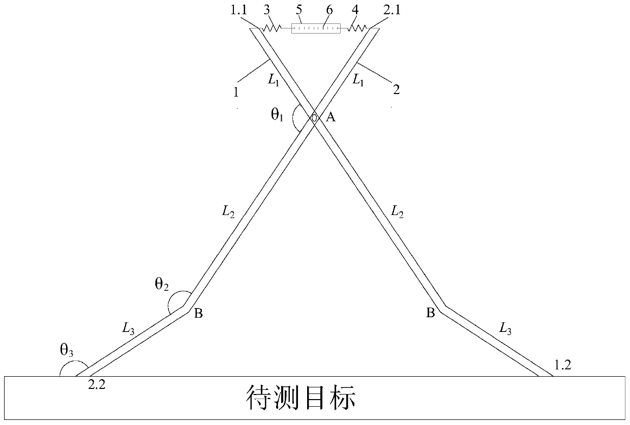
[0029] The invention provides a large-range optical fiber grating displacement monitoring device, which is characterized in that it includes: a displacement acquisition and transmission component for monitoring the real-time displacement of the target to be measured and converting the real-time displacement into a measurable displacement; The optical fiber measuring component that converts the measurable displacement into the wavelength drift of the fiber grating and measures the wavelength of the fiber grating in real time, the input end of the displacement acquisition and transfer component is connected to the target to be measured, and the output end of the displacement acquisition and transfer component Connect with the optical fiber measurement component.

[0030] The displacement monitoring device is used to measure the displacement caused by cracks and sliding caused by ...


PUM


Abstract

The invention provides a large-range fiber Bragg grating displacement monitoring device. The device is characterized by comprising a strain acquisition and transmission component and a measurement component, wherein the strain acquisition and transmission component is used for monitoring the strain of a to-be-detected target and correspondingly zooming out the strain into small strain; the measurement component is used for measuring the wavelength change of a fiber Bragg grating caused by the strain; the rear end of the strain acquisition and transmission component is connected with the to-be-detected target, and the front end of the strain acquisition component is connected with the measurement component. The device converts the large strain of the to-be-detected target object into smallstrain of the front end of the displacement acquisition and transmission device through the rear end of a displacement acquisition and transmission device by establishing a strain transmission mechanism for the large strain of a matrix and the small strain of the fiber Bragg grating; the displacement monitoring device is used for measuring the small strain of the front end of the displacement acquisition and transmission device, and finally a processor is used for calculating and obtaining the displacement corresponding to the large strain of to-be-detected target.

Description

technical field [0001] The invention relates to the field of engineering measuring tools, in particular to a large-range optical fiber grating displacement monitoring device and system. Background technique [0002] In engineering structures, large displacement responses will affect the reliability of the structure, so it is particularly important to monitor the deformation of structures such as bridges, houses, slopes, foundation pits, and pile foundations. Traditional monitoring methods have low monitoring efficiency, high measurement cost, low degree of automation and low measurement accuracy. In recent years, due to its intelligent real-time monitoring, fiber optic sensors have a huge application market in various industries. In particular, the quasi-distributed fiber Bragg grating, as the most widely used and mature fiber sensor technology, has the characteristics of light weight, small size, high precision, high temperature resistance, corrosion resistance, and intell...

Claims


Application Information

Patent Timeline
IPC IPC(8): G01B11/02
CPCG01B11/02
Inventor 郑勇朱正伟肖旺卢黎徐嘉
Owner CHONGQING UNIV
Learn More