
Testable current transformer and electrical apparatus comprising means for testing such a current transformer

A technology for current converters and electrical equipment, applied in the direction of measuring current/voltage, measuring devices, and only measuring current, etc. It can solve problems such as incompatibility of response time and difficulty in completely eliminating offsets

Pending Publication Date: 2019-11-05
SCHNEIDER ELECTRIC IND SAS
View PDF10 Cites 0 Cited by
  • Summary
  • Abstract
  • Description
  • Claims
  • Application Information

AI Technical Summary

Problems solved by technology

This solution is very simple and economical, but removing the offset present on the measurement signal may require processing time, which in this case is also incompatible with the response time required for the protection device
Also, in the case of differential measurements of weak DC signals at the winding terminals, it is difficult to completely remove the offset

Method used


Image

  • Testable current transformer and electrical apparatus comprising means for testing such a current transformer
  • Testable current transformer and electrical apparatus comprising means for testing such a current transformer
  • Testable current transformer and electrical apparatus comprising means for testing such a current transformer

Examples


Embodiment Construction

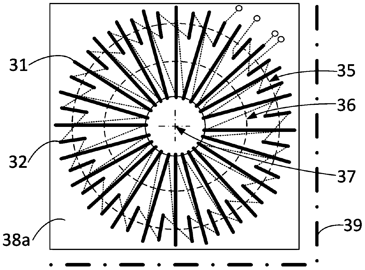
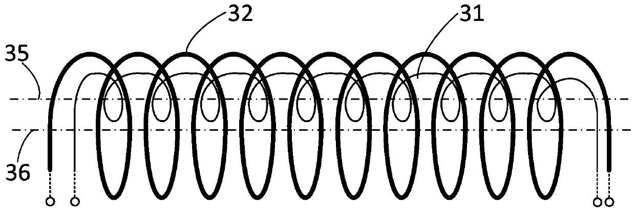
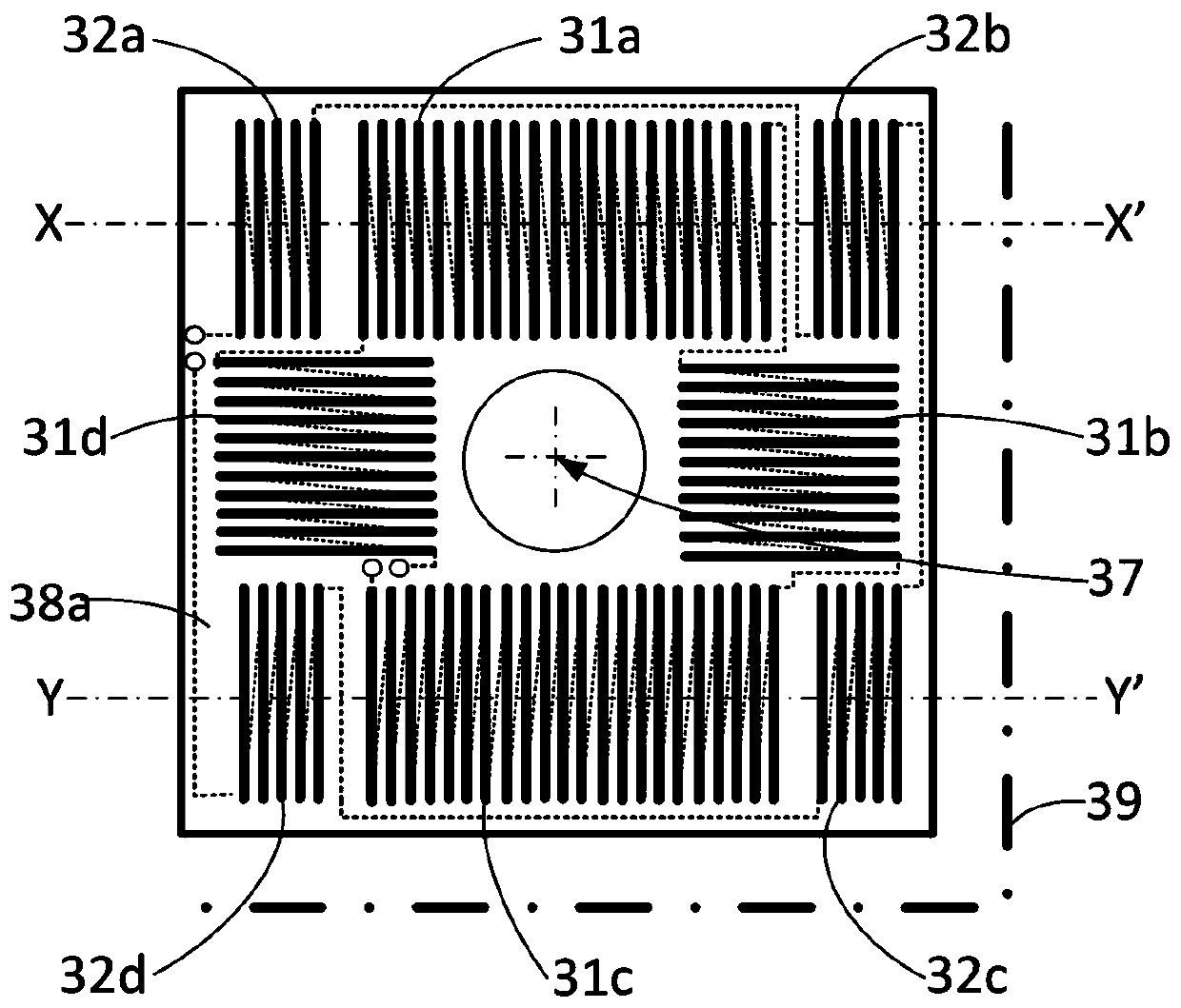
[0045] The invention relates to a Rogowski current transducer, which is intended to measure the current Ip flowing through a current conductor 2 . The current transformer is formed by a measuring secondary winding 31 which is designed to surround the current conductor 2 which forms the primary circuit. The current Ip flowing through the current conductor 2 will induce an electromagnetic flux in the measuring secondary winding 31 which, depending on the type of load used, generates a signal, current or voltage in the secondary winding 31 .

[0046] figure 1is a schematic diagram of the layout of the measurement secondary winding 31 according to the first embodiment. The measuring secondary winding 31 is arranged along a first circular winding axis 36 around a center 37 . The measuring winding 31 is formed on the first support 38a. The measurement secondary winding 31 is formed by turns, shown in solid lines when the turns are on the visible face of the first support 38a, and...


PUM


Abstract

The invention relates to a Rogowski current transformer (3) intended to measure a current (Ip) flowing through a current conductor (2). The current transformer (3) comprises a measurement secondary winding (31) and a test secondary winding (32) for inducting a test electrical signal in the measurement secondary winding (31). The pulse generator circuit (10) is connected to the test secondary winding (32) in order to generate a test pulse (61) at a predetermined test frequency (Ft) in the test secondary winding (32). The invention also relates to an electrical device comprising such a current converter. The electrical device comprises means for testing the current converter and means for generating a warning in the event of a converter failure.

Description

technical field [0001] The invention relates to a Rogowski current transformer, which is intended to measure the current flowing through a current conductor forming a primary circuit. The current transformer includes a measurement secondary winding and a test secondary winding for inductively measuring a test electronic current in the secondary winding. [0002] The invention also relates to electrical equipment comprising such a current transformer, and a device for testing the current transformer. Background technique [0003] Current sensors are used in current, power, or energy measuring equipment, and in equipment such as circuit breakers, contactors, disconnects, or other electricity meters used to protect or monitor electrical distribution facilities. One of the current sensors used is a Rogowski sensor. This type of sensor consists of a bracket made of non-magnetic material that is positioned around the electrical conductor through which the current to be measured ...

Claims


Application Information

Patent Timeline
Patent Type & Authority Applications(China)
IPC IPC(8): G01R15/18G01R35/02G01R19/00G01R31/62G01R31/72
CPCG01R15/181G01R35/02G01R19/0092G01R31/72G01R31/52G01R31/62G01R21/00G01R31/3277G01R35/00
Inventor L.乌兰卡
Owner SCHNEIDER ELECTRIC IND SAS
Learn More