Electrical connectors for circuit boards

A technology for circuit substrates and electrical connectors, applied in the directions of connection, circuit, fixed connection, etc., can solve problems such as the reduction of high-speed transmission characteristics, and achieve the effect of suppressing the reduction of high-speed transmission characteristics and realizing thinning.

Active Publication Date: 2022-04-08
HIROSE ELECTRIC GROUP
View PDF17 Cites 0 Cited by
  • Summary
  • Abstract
  • Description
  • Claims
  • Application Information

AI Technical Summary

Problems solved by technology

In the case of using a connector for high-speed signal transmission, the above-mentioned straight parts are close to each other, whereby crosstalk occurs between the straight parts, and high-speed transmission characteristics may be degraded
In addition, the larger the overlapping range of straight portions in the vertical direction, the greater the reduction in high-speed transmission characteristics.

Method used


Image

  • Electrical connectors for circuit boards
  • Electrical connectors for circuit boards
  • Electrical connectors for circuit boards

Examples


Embodiment Construction

[0027] Hereinafter, embodiments of the present invention will be described based on the drawings.

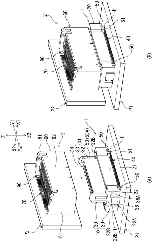
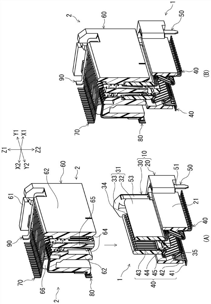
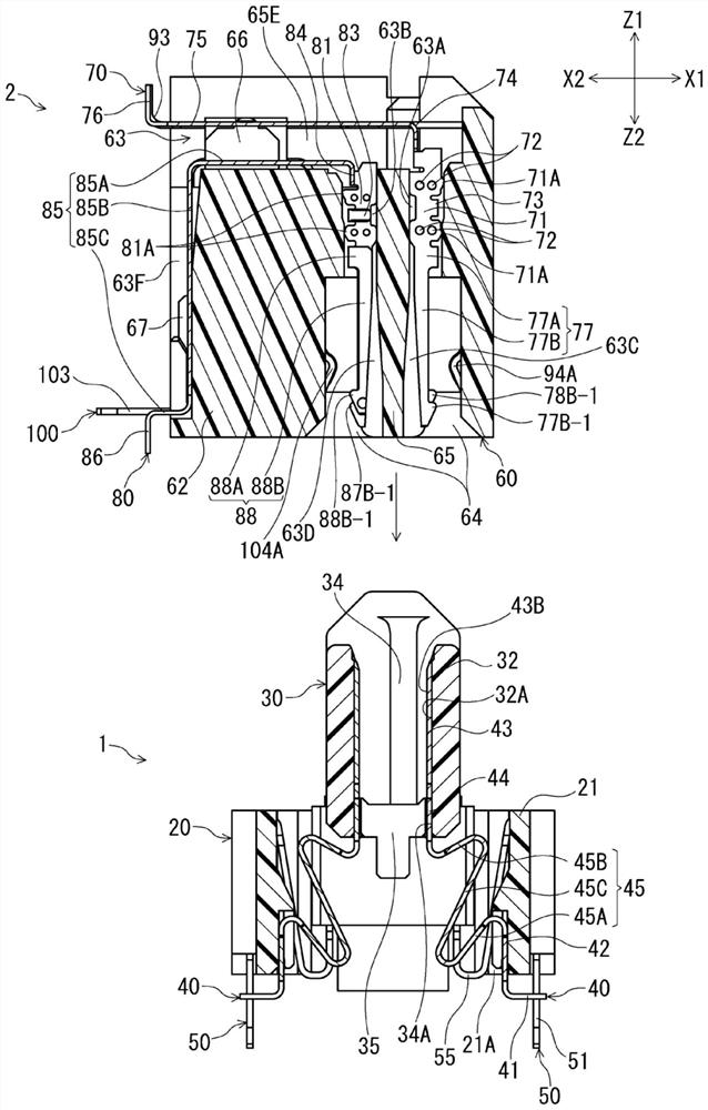
[0028] figure 1 (A) and (B) are external perspective views of a connector assembly having a plug connector and a receptacle connector fitted and connected thereto according to an embodiment of the present invention, figure 1 (A) represents the state before chimera connection, and figure 1 (B) shows the state after chimera connection. figure 2 (A) and (B) are cross-sectional perspective views of the position of the signal terminals of the two connectors (plug connector and socket connector) in the terminal arrangement direction, figure 2 (A) shows the state before fitting connection with a cross section at right angles to the terminal arrangement direction, figure 2 (B) shows the state after fitting connection by the cross section perpendicular|vertical to the terminal arrangement direction. image 3 and Figure 4 It is a cross-sectional view of the position of the signa...


PUM


Abstract

The present invention provides an electrical connector for a circuit board capable of securing a sufficient amount of floating, reducing the thickness of the connector, and minimizing degradation of high-speed transmission characteristics. The terminal (40) has: a fixed side held portion (42) held by the fixed case (20); a movable side held portion (44) held by the movable case (30); and an elastic portion (45) , arranged between the fixed-side held portion (42) and the movable-side held portion (44), the elastic portion (45) of the elastic portion (45) in the longitudinal direction of the terminal (40) A portion has bent portions (45A, 45B) bent so as to have portions repeatedly arranged in a connector height direction at right angles to the mounting surface of the circuit board.

Description

technical field [0001] The present invention relates to an electrical connector for a circuit board arranged on a mounting surface of a circuit board. Background technique [0002] As a connector for a circuit board, for example, the connector of Patent Document 1 is known. The connector of this patent document 1 is fitted and connected to the counterpart connector in the vertical direction at right angles to the mounting surface of the circuit board, and is allowed to be connected to the counterpart in the direction parallel to the above-mentioned mounting surface by the elastic displacement of the terminal. So-called floating connectors where the position of the connector is shifted. The connector housing includes a fixed housing fixed to a circuit board via terminals, and a movable housing formed as a separate component from the fixed housing and movable relative to the fixed housing. In addition, the terminals are arranged in two rows, and a connection portion for conn...

Claims


Application Information

Patent Timeline
Patent Type & Authority Patents(China)
IPC IPC(8): H01R12/91H01R13/02H01R13/627H01R13/629
CPCH01R12/91H01R13/02H01R13/627H01R13/629H01R12/57H01R12/737H01R24/60H01R13/631H01R13/6315H01R13/24H01R13/422H01R12/727
Inventor 堀井崇生
Owner HIROSE ELECTRIC GROUP
Why Eureka
Try Eureka