

Calibration method of optical sensor in bluetooth earphone and bluetooth earphone
A technology of optical sensor and bluetooth earphone, which is applied in the direction of sensor, earphone mechanical/electronic switch, microphone, etc. It can solve the problems of low efficiency, easy interference in the calibration process, and increased cost, so as to achieve the effect that it is not easy to be interfered
- Summary
- Abstract
- Description
- Claims
- Application Information
AI Technical Summary
Problems solved by technology
Method used
Image

Examples
Embodiment 1
[0039] Please refer to figure 1 , Embodiment 1 of the present invention provides a method for calibrating an optical sensor in a Bluetooth headset, the method is applicable to the scene of calibrating the optical sensor in the Bluetooth headset, and the method is composed of a Bluetooth headset and a charging box adapted to the Bluetooth headset The Bluetooth headset includes an optical sensor and a command execution device, and a command initiation device and a command transmission medium are arranged in the charging box. The method specifically includes the following steps:
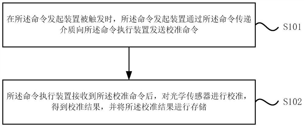
[0040] S101. When the command initiating device is triggered, the command initiating device sends a calibration command to the command executing device through the command transmission medium.
[0041] Wherein, the manner in which the command initiating device is triggered includes, but is not limited to, any one or a combination of the following manners:
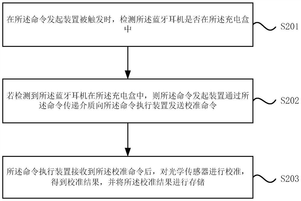
[0042] (1) If the charging box receives a co...
Embodiment 2
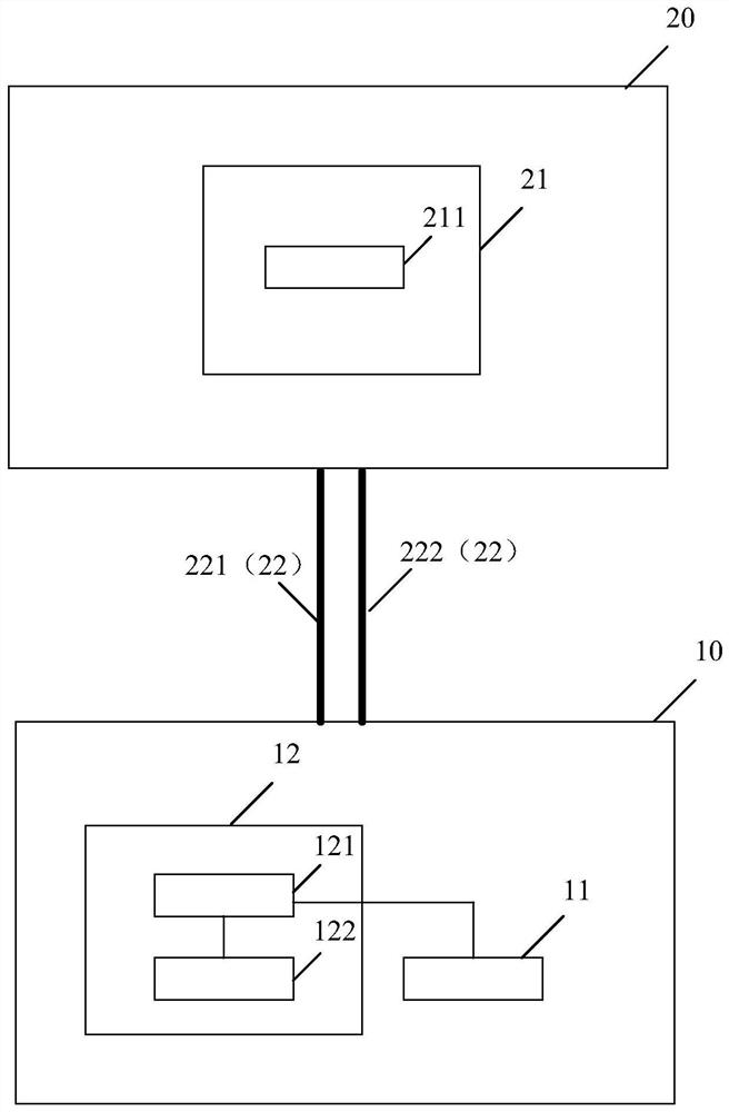
[0057] An embodiment of the present invention provides a bluetooth earphone, using the optical sensor calibration method in the bluetooth earphone as described in Embodiment 1 to perform optical sensor calibration processing, the bluetooth earphone 10 includes a housing and an optical sensor 11 accommodated in the housing and command execution device 12; wherein,
[0058] After the Bluetooth headset 10 is loaded into the charging box 20 adapted to the Bluetooth headset 10, it is connected to the charging box 20; the charging box 20 includes a shell and a command initiation device 21 contained in the shell and Command delivery medium 22;
[0059] The command initiating device 21 and the command transmission medium 22 are used to send a calibration command to the command executing device 12;
[0060] The command execution device 12 is used for calibrating the optical sensor 11 .
[0061] Specifically, the command initiation device 21 includes a first control unit 211, the comm...
PUM
 Abstract
Description
Claims
Application Information