Punching device for agricultural planting

A punching device and agricultural technology, applied in agriculture, planting methods, fertilization devices, etc., can solve the problems of reduced operation efficiency, low efficiency, and no improvement of punching efficiency, so as to avoid hole collapse, improve operation efficiency, and improve The effect of the hole punch effect

Active Publication Date: 2019-11-08
张善科 +1
View PDF5 Cites 13 Cited by
  • Summary
  • Abstract
  • Description
  • Claims
  • Application Information

AI Technical Summary

Problems solved by technology

[0002] The commonly used planting method for punching, the traditional manual punching method, is inefficient, and the punched holes are prone to collapse. When it is necessary to sow, it is necessary to repeatedly punch holes, which furth...

Method used


Image

  • Punching device for agricultural planting
  • Punching device for agricultural planting
  • Punching device for agricultural planting

Examples


Embodiment 1

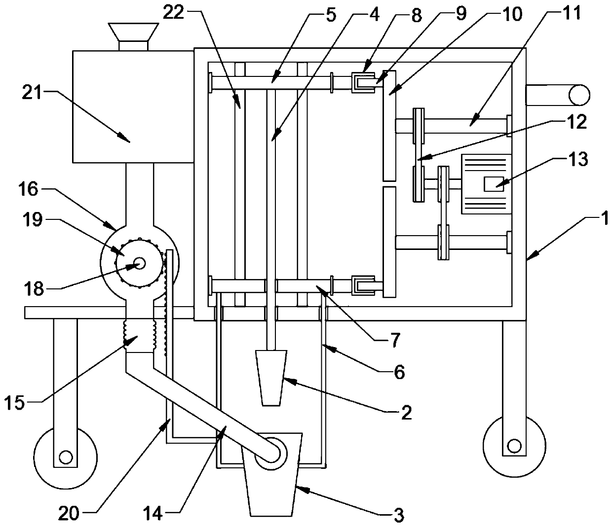
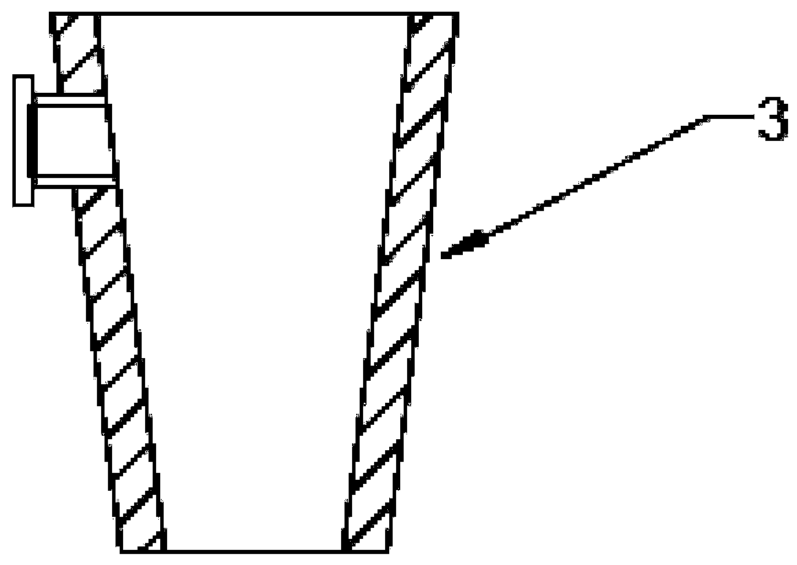
[0021] see Figure 1-4 , in an embodiment of the present invention, a punching device for agricultural planting, comprising a frame 1; a punching cone 2 is provided below the frame 1, and the punching cone 2 is a solid circular frustum and the diameter of the lower end is smaller than the diameter of the upper end. The upper end of the punching cone 2 is connected with the upper lifting plate 5 through the first connecting rod 4; the bottom of the punching cone 2 is provided with a reaming cylinder 3, the reaming cylinder 3 is a hollow circular table tube with upper and lower openings, and the opening at the lower end of the reaming cylinder 3 The diameter is greater than the diameter of the upper end of the perforating cone 2, so that the perforating cone 2 can pass through the reaming cylinder 3; the reaming cylinder 3 is fixedly connected with the lower lifting plate 7 by the second connecting rod 6; the upper lifting plate 5 and the lower lifting plate 7 are all run throug...

Embodiment 2

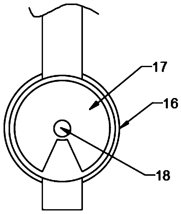
[0024] The difference between this embodiment and Embodiment 1 is that: the outer wall of the reaming cylinder 3 is hinged with a connecting pipe 14, and the connecting pipe 14 communicates with the inner cavity of the reaming cylinder 3; Material barrel 16, lower material barrel 16 is the cylinder that vertically arranges, and lower material cylinder 16 is nested with lower material roller 17, and lower material roller 17 is provided with fan-shaped gap, rotates in lower material cylinder 16 by lower material roller 17, realizes Material blanking; the upper end of the feeding cylinder 16 is connected with a material box 21, the material box 21 is fixedly connected with the vehicle frame 1, and seeds or granular fertilizers can be filled in the material box 21; the material box 21 is fixedly connected with a shaft Roller 18, shaft roller 18 is connected with driving mechanism, and driving mechanism drives blanking roller 17 to rotate, and then realizes blanking.

[0025] The d...


PUM


Abstract

The invention discloses a punching device for agricultural planting. The punching device comprises a frame, a punching cone is arranged below the frame, the upper end of the punching cone is connectedwith an upper lifting plate through a first connection rod, a chambering barrel is arranged below the punching cone and fixedly connected with a lower lifting plate through a second connection rod, and both the upper lifting plate and the lower lifting plate are connected with a lifting driving mechanism. Through the punching cone, the chambering barrel, the upper lifting plate, the lower liftingplate and the lifting driving mechanism, up-down reciprocating movement of the punching cone and the chambering barrel is realized; holes are chambered and compacted after punching, so that punchingeffect is improved, collapse of the holes is avoided, and convenience is brought to subsequent operation; through a connection pipe, a gear disc, a rack plate and a discharging barrel with a discharging roller nested inside, linkage of the discharging roller and the chambering barrel is realized, and seeding or applying of granular fertilizer is realized during chambering, so that operation efficiency is improved.

Description

technical field [0001] The invention relates to the field of agricultural planting machinery, in particular to a punching device for agricultural planting. Background technique [0002] The commonly used planting method for punching, the traditional manual punching method, is inefficient, and the punched holes are prone to collapse. When it is necessary to sow, it is necessary to repeatedly punch holes, which further reduces the efficiency of the operation. This application provides a mechanical punching method. The hole device not only improves the punching efficiency but also improves the quality of punching, which is convenient for follow-up operations. Contents of the invention [0003] The object of the present invention is to provide a punching device for agricultural planting, so as to solve the problems raised in the above-mentioned background technology. [0004] To achieve the above object, the present invention provides the following technical solutions: [00...

Claims


Application Information

Patent Timeline
IPC IPC(8): A01C5/04A01C7/00A01C7/20A01C15/16
CPCA01C5/04A01C7/002A01C7/20A01C15/16
Inventor 不公告发明人
Owner 张善科
Why Eureka
Try Eureka