Uniform flow-guiding pyrolysis reaction device for urea and high-temperature flue gas

A technology of high temperature flue gas and reaction equipment, which is applied in the chemical method of reacting liquid and gas medium, the preparation/separation of ammonia, inorganic chemistry, etc. Reaction, reducing pyrolysis efficiency and other problems, to achieve the effect of enhancing urea pyrolysis effect and pyrolysis speed, avoiding the reduction of urea pyrolysis reaction efficiency, and increasing the spraying area

Inactive Publication Date: 2019-11-08
郑州林大环保科技有限公司
View PDF0 Cites 1 Cited by
  • Summary
  • Abstract
  • Description
  • Claims
  • Application Information

AI Technical Summary

Problems solved by technology

[0003] However, in the traditional urea pyrolysis device, when the pyrolysis reaction is carried out, when the high-temperature flue gas and the sprayed urea solution are pyrolyzed, the reaction area of ​​the pyrolysis contact is small, and the sufficient pyrolysis reaction cannot be carried out, and the pyrolysis is uniform. The temperature will also be greatly reduced, and in the process of flue gas diversion, heat loss will occur. The temperature of the flue gas reaching the interior of the pyrolysis chamber will gradually decrease, and the time to participate in the pyrolysis reaction is shorter, which not only reduces the temperature of the pyrolysis Efficiency, but also cause a decline in the quality of urea pyrolysis

Method used


Image

  • Uniform flow-guiding pyrolysis reaction device for urea and high-temperature flue gas
  • Uniform flow-guiding pyrolysis reaction device for urea and high-temperature flue gas
  • Uniform flow-guiding pyrolysis reaction device for urea and high-temperature flue gas

Examples


Embodiment 1

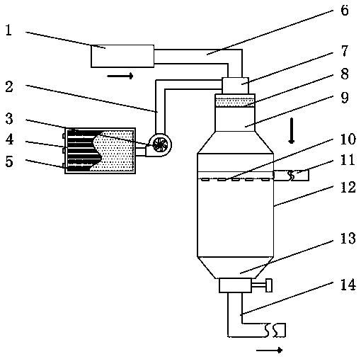
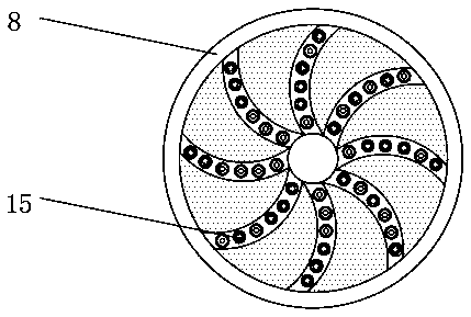
[0021] Embodiment one, by Figure 1-3 Given, the present invention includes a high-temperature flue gas inlet 1 and a pyrolysis reaction chamber 12, one side of the high-temperature flue gas inlet 1 is connected with a flue gas pipe 6, and one end of the flue gas pipe 6 is provided with a heating chamber 7, and the heating chamber 7 A diffusion section 9 is provided at the bottom, and the bottom of the diffusion section 9 is connected through the pyrolysis reaction chamber 12. A deflector 8 is installed inside the diffusion section 9, and a flue gas guide port 15 is provided on the surface of the deflector 8. The deflector 8 has a circular structure, and the thickness of the deflector 8 is 5-10 cm. There are a plurality of smoke guide ports 15, and the plurality of smoke guide ports 15 are distributed in a ring and equidistant.

[0022] Specifically, through the plurality of flue gas guide ports 15 on the circular deflector 8, the incoming flue gas can be effectively divided i...

Embodiment 2

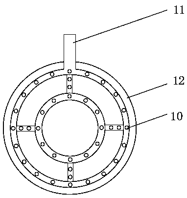
[0023] Embodiment 2, on the basis of Embodiment 1, one side of the pyrolysis reaction chamber 12 is provided with a urea atomization spray gun 11, and the urea atomization spray gun 11 extends to the inside of the pyrolysis reaction chamber 12, and the urea atomization Atomizing nozzles 10 are arranged on the surface of the spray gun 11, and there are a plurality of atomizing nozzles 10, and the plurality of atomizing nozzles 10 are distributed equidistantly in a ring.

[0024] Specifically, the surface of the annularly distributed urea atomizing spray gun 11 is equidistantly provided with a plurality of atomizing nozzles 10, which can effectively increase the spraying area of ​​the urea solution, so that the pyrolysis reaction between the urea solution molecules and the high-temperature flue gas is more sufficient, The reaction efficiency of urea pyrolysis is improved.

Embodiment 3

[0025] Embodiment 3, on the basis of Embodiment 1, a heating device 4 is provided on one side of the pyrolysis reaction chamber 12, and a plurality of heating fins 5 are installed inside the heating device 4, and a suction device is installed on one side of the heating device 4. Fan 3, and one end of the suction fan 3 is equipped with an air guide pipe 2, and one end of the air guide pipe 2 is connected through the heating chamber 7, and one side of the heating device 4 is provided with an air inlet.

[0026] Specifically, heat is generated through the heating fins 5 inside the heating device 4, and under the adsorption of the suction fan 3, the heat inside the heating device 4 is guided into the inside of the heating chamber 7 through the air guide pipe 2, and the flue gas is guided. The heat lost in the process is supplemented by heat, so that the flue gas can have enough heat to enter the interior of the pyrolysis reaction chamber 12 to perform a sufficient pyrolysis reactio...


PUM

PropertyMeasurementUnit
thicknessaaaaaaaaaa

Abstract

The invention discloses a uniform flow-guiding pyrolysis reaction device for urea and high-temperature flue gas. The device comprises a high-temperature flue gas inlet and a pyrolysis reaction chamber; and one side of the high-temperature flue gas inlet communicates with a flue gas pipeline, one end of the flue gas pipeline is provided with a heating chamber, and the bottom of the heating chamberis provided with a diffusion section. According to the device provided by the invention, a circular flow-guiding plate is arranged in the diffusion section, in the process of a pyrolysis reaction of the urea, the flue gas which enters the device can be effectively divided into a plurality of small gas flows through a plurality of flue gas flow-guiding openings in the circular flow-guiding plate, the small gas flows are uniformly released and enters the interior of the pyrolysis reaction chamber, a plurality of atomizing spray nozzles are equidistantly arranged and annularly distributed at thesurface of a urea atomizing spray gun, so that the spraying area of the urea solution can be effectively increased, the pyrolysis reaction of the urea solution molecules and the high-temperature fluegas is more full, and the uniformity of urea pyrolysis and the reaction efficiency of pyrolysis are greatly improved.

Description

technical field [0001] The invention relates to the technical field of urea pyrolysis, in particular to a uniform diversion and pyrolysis reaction equipment for urea high-temperature flue gas. Background technique [0002] With the rapid development of industrialization, nitrogen oxides (NOx) have become one of the main pollutants in the atmosphere. In the process of atmospheric nitrogen oxides treatment, the selective catalytic reduction technology (SCR) is mainly used for the treatment of nitrogen oxides. SCR Generally, there are three kinds of reducing agents, urea, ammonia water and liquid ammonia. Liquid ammonia is highly dangerous and generally not used as a catalyst. There are two processes for producing ammonia from urea, pyrolysis process and hydrolysis process. Due to the incompleteness of the hydrolysis reaction, the loss of ammonia gas or insufficient ammonia production reaction will lead to a decrease in denitrification efficiency, so ammonia production is usu...

Claims


Application Information

Patent Timeline
Patent Type & Authority Applications(China)
IPC IPC(8): B01D53/90B01D53/86B01D53/56C01C1/08B01J10/00
CPCB01D53/8631B01D53/90B01J10/00C01C1/086
Inventor 肖学德王庆伟杨蕾牛丽萍金超杨冬冬刘盈盈王玉华郭阳洋李鹏袁利杰苏朝
Owner 郑州林大环保科技有限公司
Why Eureka
Try Eureka