Concrete hoisting system for buildings

A lifting system and concrete technology, applied in clay preparation devices, cement mixing devices, unloading devices, etc., can solve the problems of no good debugging mechanism, no steam curing mechanism, poor flexibility in use of concrete lifting equipment, etc.

Inactive Publication Date: 2019-11-08
珠海神工建设工程有限公司
View PDF0 Cites 3 Cited by
  • Summary
  • Abstract
  • Description
  • Claims
  • Application Information

AI Technical Summary

Problems solved by technology

[0003] The object of the present invention is to provide a kind of concrete lifting system for construction, to solve the above-mentioned problems in the background technology. In the construction engineering operation, the traditional concrete lifting equipment is prone to blockage when feeding materials, and it does not have good mixing. Mechanism, in the face of dry concrete, there is no integrated steam curing mechanism, so that the concrete needs to be processed many times before use, and there is no good debugging mechanism when discharging, which makes the use of concrete lifting equipment more flexible poor problem

Method used


Image

  • Concrete hoisting system for buildings
  • Concrete hoisting system for buildings
  • Concrete hoisting system for buildings

Examples


Embodiment 1

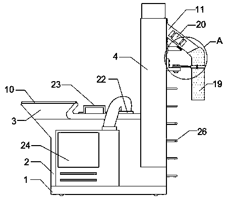
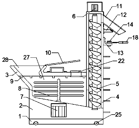
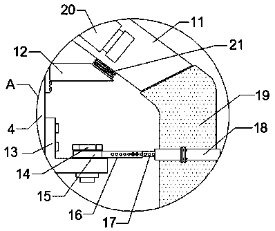
[0017] like Figure 1-3 As shown, a concrete lifting system for construction includes a base 1, a material box 2, a feeding cylinder 4 and a steam generator 24, the top side of the base 1 is welded with a material box 2, and one end of the material box 2 is fixedly welded There is a feeding cylinder 4, a screw push rod 5 is installed through a bearing in the described feeding cylinder 4, and a rotating motor 6 is installed on the top of the described feeding cylinder 4 through a bolt, and the driving end of the rotating motor 6 is connected to the screw pushing rod 5 The rotating shaft is connected, and one side of the bottom of the material box 2 is connected through the feeding cylinder 4. The inner top of the material box 2 is provided with a slope-type material tank 27, and a stirring rod 8 is installed through a bearing in the slope-type material tank 27. The bottom of the feed box 2 is embedded with a drive motor 7 by bolts, the drive end of the drive motor 7 is connecte...

Embodiment 2

[0025] like Figure 1-3 As shown, a concrete lifting system for construction includes a base 1, a material box 2, a feeding cylinder 4 and a steam generator 24, the top side of the base 1 is welded with a material box 2, and one end of the material box 2 is fixedly welded There is a feeding cylinder 4, a screw push rod 5 is installed through a bearing in the described feeding cylinder 4, and a rotating motor 6 is installed on the top of the described feeding cylinder 4 through a bolt, and the driving end of the rotating motor 6 is connected to the screw pushing rod 5 The rotating shaft is connected, and one side of the bottom of the material box 2 is connected through the feeding cylinder 4. The inner top of the material box 2 is provided with a slope-type material tank 27, and a stirring rod 8 is installed through a bearing in the slope-type material tank 27. The bottom of the feed box 2 is embedded with a drive motor 7 by bolts, the drive end of the drive motor 7 is connecte...


PUM


Abstract

The invention discloses a concrete hoisting system for buildings. The concrete hoisting system for the buildings comprises a base, a material box, a feeding barrel and a steam generator. The materialbox is arranged on one side of the top of the base in a welded manner. The feeding barrel is fixedly welded to one end of the material box. A spiral material-pushing rod is installed in the feeding barrel through bearings. A rotary motor is installed at the top end of the feeding barrel through bolts. The driving end of the rotary motor is connected with a rotary shaft of the spiral material-pushing rod. One side of the bottom of the material box is connected with the feeding barrel in a penetrating manner. A slope type material groove is formed in the top inside the material box. Stirring rods are installed in the slope type material groove through bearings. A driving motor is installed and arranged at the bottom of the material box in an embedded manner. The driving end of the driving motor is connected with a rotary shaft of the stirring rods. A groove cover is arranged on the top of the slope type material groove in a covering manner. By means of the concrete hoisting system for the buildings, debugging of concrete hoisting discharging work can be more flexible, curing and mixing uniformity of the concrete can be achieved integrally, and the use quality of the concrete is improved greatly.

Description

technical field [0001] The invention belongs to the technical field of construction, and in particular relates to a concrete lifting system for construction. Background technique [0002] In construction engineering operations, traditional concrete lifting equipment is prone to clogging when feeding materials. It does not have a good mixing mechanism. When faced with dry concrete, it does not have an integrated steam curing mechanism, which makes concrete need to be used before use. Multiple treatments are carried out, and there is no good debugging mechanism when discharging, which makes the use flexibility of the concrete lifting equipment poor. Contents of the invention [0003] The object of the present invention is to provide a kind of concrete lifting system for construction, to solve the problem proposed in the background technology above. Mechanism, in the face of dry concrete, there is no integrated steam curing mechanism, so that the concrete needs to be process...

Claims


Application Information

Patent Timeline
Patent Type & Authority Applications(China)
IPC IPC(8): B28C5/08B28C5/16B28C5/46B28C7/16
CPCB28C5/0856B28C5/16B28C5/466B28C7/16B28C7/167
Inventor 郭振锋吴海芳沈小议
Owner 珠海神工建设工程有限公司
Why Eureka
Try Eureka