Eureka AIR delivers breakthrough ideas for toughest innovation challenges, trusted by R&D personnel around the world.

Fiber bundle tension reducing mechanism for automatic fiber placing machine

A technology for automatic laying and tow, applied in the field of tow tension reduction mechanism of automatic laying machine, can solve the problems of reduced forming speed, fiber bridging, poor forming quality, etc., and achieve the effect of preventing accidents

Pending Publication Date: 2019-11-08
肖睿
View PDF0 Cites 3 Cited by
  • Summary
  • Abstract
  • Description
  • Claims
  • Application Information

AI Technical Summary

Problems solved by technology

[0011] In order to solve the technical problems of fiber bridging defects often occurring in the process of laying prepreg with tension on the concave surface, resulting in a decrease in molding speed and poor molding quality, the present invention further provides an automatic laying machine tow Tension reduction mechanism

Method used


Image

  • Fiber bundle tension reducing mechanism for automatic fiber placing machine
  • Fiber bundle tension reducing mechanism for automatic fiber placing machine
  • Fiber bundle tension reducing mechanism for automatic fiber placing machine

Examples


Embodiment 1

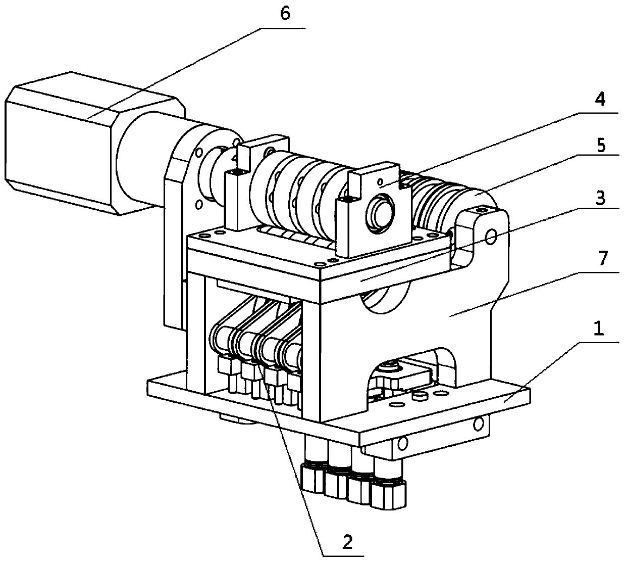
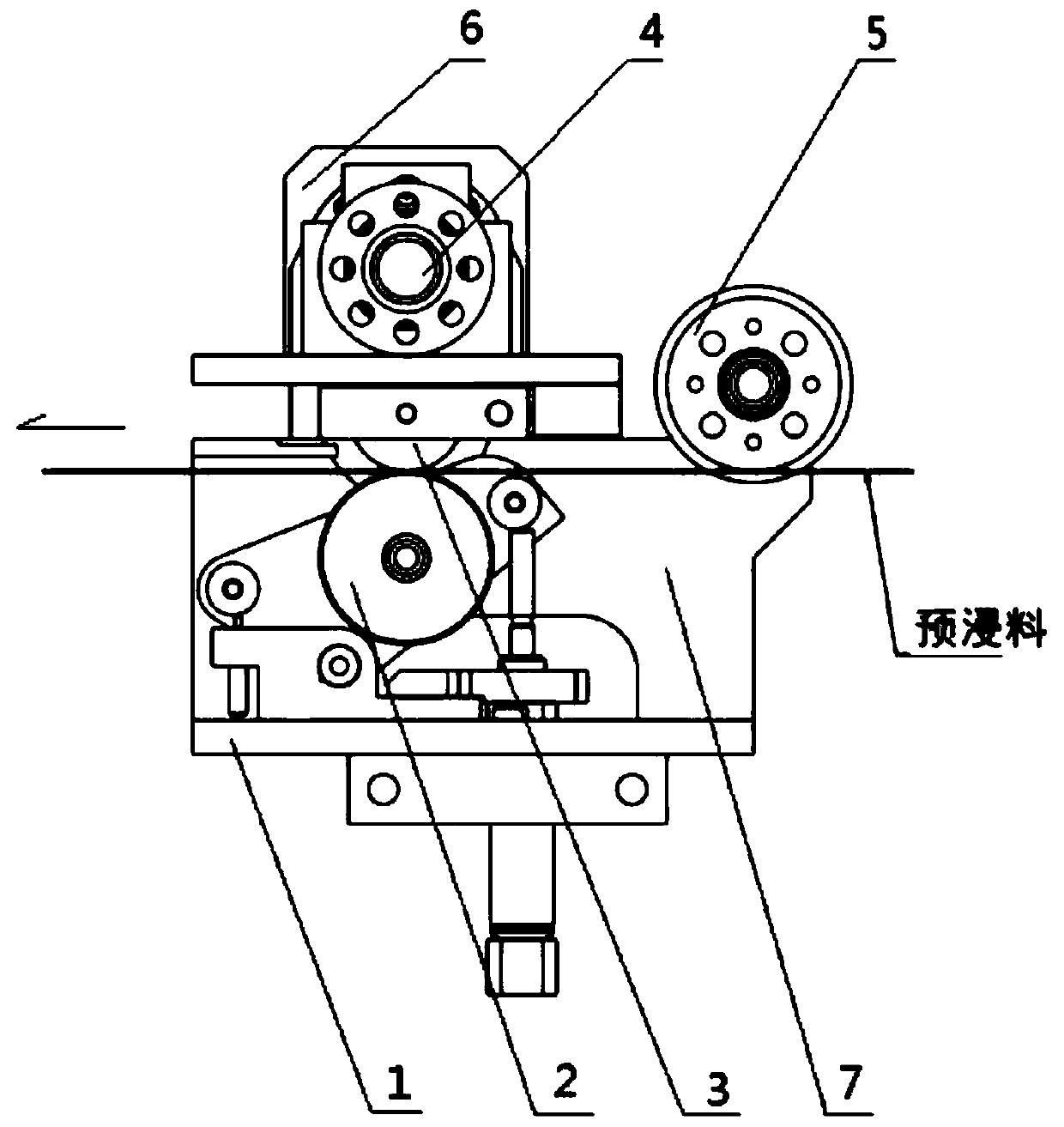
[0031] Embodiment one, combined with the attached figure 1 and 3 Explanation: a tow tension reduction mechanism of an automatic laying machine, including: a base 1, a yarn stop wheel assembly 2, an intermediate wheel assembly 3, a friction wheel assembly 4, a guide wheel assembly 5 and a tension reduction motor assembly 6,

[0032] The upper end surface of the base 1 is provided with a yarn stop wheel assembly 2, and both sides of the yarn stop wheel assembly 2 are provided with support plates 7, both ends of the guide wheel assembly 5 are connected with the support plate 7, and the upper end of the support plate 7 is equipped with an intermediate wheel assembly 3. The friction wheel assembly 4 is installed on the intermediate wheel assembly 3. The friction wheel assembly 4 is used in conjunction with the intermediate wheel assembly 3 for power transmission. The tension reduction motor assembly 6 is installed on the side wall of the support plate 7. The tension reduction motor...

Embodiment 2

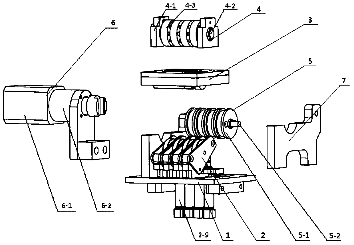
[0033] Embodiment two: on the basis of embodiment one in conjunction with Figure 4To illustrate, the yarn stop wheel assembly 2 is a plurality of yarn stop wheel mechanisms connected side by side, and the yarn stop wheel mechanism includes: hinge support 2-1, hinge shaft 2-2, spring plunger 2-3, and yarn stop wheel 2 -4, one-way bearing 2-5, yarn stop cylinder support column 2-6, spring plunger support column 2-7 and mounting plate 2-8, hinge support 2-1 is installed on the base 1, hinge support The hinge shaft 2-2 is installed on the left and right side walls of the seat 2-1, and the both sides of the hinge support 2-1 are provided with a mounting plate 2-8, and the side walls of the mounting plate 2-8 are connected with the hinge shaft 2-2, and the mounting plate The middle part of 2-8 is equipped with a yarn stop wheel rotating shaft 2-10, and the yarn stop wheel 2-4 is installed on the yarn stop wheel rotating shaft 2-10 through a one-way bearing 2-5, and the two ends of ...

Embodiment 3

[0034] Embodiment three: on the basis of embodiment two in conjunction with figure 2 To illustrate, the guide wheel assembly 5 includes a guide wheel 5-1 and a guide shaft 5-2, the two ends of the guide shaft 5-2 are connected to the support plate 7, and the axis of the guide shaft 5-2 is connected to the yarn stop wheel shaft 2. The axes of -10 are parallel to each other, and the guide shaft 5-2 is equipped with a plurality of guide wheels 5-1, and the number of the guide wheels 5-1 is the same as that of the pressing wheels 2-4 and the positions are corresponding.


PUM


Abstract

The invention relates to a fiber bundle tension reducing mechanism for an automatic fiber placing machine, and belongs to the technical field of fiber placing machines. The mechanism is characterizedin that a pressing wheel assembly is arranged on the upper end surface of a base, the two ends of a guiding wheel assembly are connected with supporting plates, the upper ends of the supporting platesare provided with a middle wheel assembly, the middle wheel assembly is provided with a friction wheel assembly, the friction wheel assembly is matched with the middle wheel assembly for power transmission, and tension reducing motor assemblies are arranged on the side walls of the supporting plates and are used for providing power for the friction wheel assembly. According to the mechanism, in order to reduce the tension of a prepreg in the automatic fiber placing process so as to realize complex curved surface laying, a tension reducing mechanism is additionally arranged in a fiber placinghead, so that the fiber tension at a pressure roller is reduced; and a middle wheel can float up and down, when the middle wheel does not work, namely a pressing wheel does not need to press a carbonfiber, the middle wheel can fall down due to gravity, but due to the limiting of a floating baffle plate, the falling distance of the middle wheel is only used for the middle wheel to be separated from a friction wheel, so that accidents are effectively prevented.

Description

technical field [0001] The invention relates to the technical field of wire laying machines, in particular to an automatic wire laying machine tow tension reducing mechanism. Background technique [0002] Automatic wire laying technology has been widely used and developed in the past 30 years, and has become a typical representative of composite material forming automation technology. Compared with automatic tape laying technology, automatic wire laying process has better adaptability and can be used to manufacture composite parts with complex curved surfaces. As far as the wire laying machine is concerned, the configuration of the laying head of each manufacturer is different but the basic functions are similar. They can complete the roller laying, yarn feeding, yarn breaking, yarn stopping, tension control, temperature control and laying pressure control, etc. Features. [0003] In practical applications, the wire laying process often has insufficient adaptability to cur...

Claims


Application Information

Patent Timeline
Patent Type & Authority Applications(China)
IPC IPC(8): B29C70/38
CPCB29C70/382
Inventor 肖睿
Owner 肖睿
Why Eureka
Eureka Blog
Learn More