A kind of steel binding device

A technology for binding steel bars and shells, which is applied in the parts and packaging of binding machinery, and can solve the problems of sore hands, complicated operation and time-consuming.

Active Publication Date: 2021-05-18
赣州市榕盛新型建材有限公司
View PDF6 Cites 0 Cited by
  • Summary
  • Abstract
  • Description
  • Claims
  • Application Information

AI Technical Summary

Problems solved by technology

[0006] In order to overcome the disadvantages of cutting the bundled iron wire to a suitable length according to the amount of steel bars that need to be bundled, the operation is more complicated and time-consuming, and tightening the wire for a long time will cause sore hands. The technical problem to be solved is: to provide a The wire cutter tightens the iron wire, which can automatically cut off the iron wire according to the number of steel bars, so that it can quickly and conveniently bind the steel bars.

Method used


Image

  • A kind of steel binding device
  • A kind of steel binding device

Examples


Embodiment 1

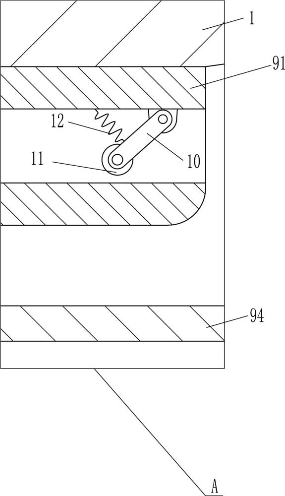
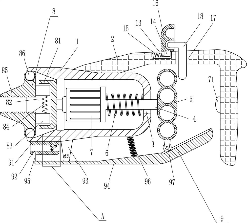
[0019] A rebar binding device, such as figure 1 As shown, it includes a cylindrical shell 1, a handle 2, a T-shaped slide bar 4, a handle 5, a first spring 6, a drive motor 7, a switch 71 and a clamping device 8, and a handle 2 is installed on the outer surface of the cylindrical shell 1. , the cylindrical shell 1 is connected with the handle 2 by means of bolt connection, the left side of the cylindrical shell 1 is open, the inner left side of the cylindrical shell 1 is a slope, and the right side of the cylindrical shell 1 has a sliding hole 3 for sliding The sliding type in the hole 3 is provided with a T-shaped slide bar 4, and the right end of the T-shaped slide bar 4 is equipped with a handle 5, and the handle 5 is located on the right side of the cylindrical shell 1, between the T-shaped slide bar 4 and the inner right side of the cylindrical shell 1 A first spring 6 is connected, and a drive motor 7 is installed on the left side of the T-shaped slide bar 4. The T-shape...

Embodiment 2

[0024] A rebar binding device, such as Figure 1-2 As shown, it includes a cylindrical shell 1, a handle 2, a T-shaped slide bar 4, a handle 5, a first spring 6, a drive motor 7, a switch 71 and a clamping device 8, and a handle 2 is installed on the outer surface of the cylindrical shell 1. , the left side of the cylindrical shell 1 is an open type setting, the left side of the cylindrical shell 1 is a slope, the right side of the cylindrical shell 1 has a sliding hole 3, and the sliding type in the sliding hole 3 is provided with a T-shaped slide bar 4, T The right end of the type slide bar 4 is equipped with a handle 5, and the handle 5 is located on the right side of the cylindrical shell 1, and the first spring 6 is connected between the T-shaped slide bar 4 and the inner right side of the cylindrical shell 1, and the left side of the T-shaped slide bar 4 A drive motor 7 is installed, and the drive motor 7 is located in the cylindrical shell 1. A switch 71 is installed in...

Embodiment 3

[0031] A rebar binding device, such as Figure 1-2 As shown, it includes a cylindrical shell 1, a handle 2, a T-shaped slide bar 4, a handle 5, a first spring 6, a drive motor 7, a switch 71 and a clamping device 8, and a handle 2 is installed on the outer surface of the cylindrical shell 1. , the left side of the cylindrical shell 1 is an open type setting, the left side of the cylindrical shell 1 is a slope, the right side of the cylindrical shell 1 has a sliding hole 3, and the sliding type in the sliding hole 3 is provided with a T-shaped slide bar 4, T The right end of the type slide bar 4 is equipped with a handle 5, and the handle 5 is located on the right side of the cylindrical shell 1, and the first spring 6 is connected between the T-shaped slide bar 4 and the inner right side of the cylindrical shell 1, and the left side of the T-shaped slide bar 4 A drive motor 7 is installed, and the drive motor 7 is located in the cylindrical shell 1. A switch 71 is installed in...


PUM


Abstract

The invention relates to a binding device, in particular to a steel bar binding device. The technical problem to be solved is: to provide a steel bar binding device which can automatically cut the iron wire according to the quantity of the steel bars without manually tightening the iron wires with wire cutters, and can quickly and conveniently bind the steel bars. The technical embodiment of the present invention is: a steel bar binding device, including a cylindrical shell, a handle, a T-shaped slide bar, etc.; The left side of the body is an inclined plane, and the right side of the cylindrical shell is provided with a slide hole, and a T-shaped slide bar is provided for sliding in the slide hole. The present invention can clamp the iron wire through the clamp block, drive the motor to drive the clamp block to rotate, so that the iron wire can be tightened, and the connecting rod can be driven to drive the cutter to cut the iron wire through the movement of the handle. The steel bars are bundled, and the iron wires can be quickly cut and tightened.

Description

technical field [0001] The invention relates to a binding device, in particular to a steel bar binding device. Background technique [0002] Steel bar refers to the steel used for reinforced concrete and prestressed reinforced concrete. Its cross section is circular, sometimes square with rounded corners, including smooth round steel bar, ribbed steel bar, and twisted steel bar. [0003] Steel bars for reinforced concrete refer to the straight or coiled steel used for reinforced concrete reinforcement. Its shape is divided into two types: smooth round steel bar and deformed steel bar. The delivery state is straight bar and coiled round. [0004] In the process of transportation and installation, the straight steel bars are generally delivered one at a time; when multiple pieces are delivered together, they should be tied firmly and fastened with ropes for lifting. The delivery personnel must not stand vertically below the delivered steel bars. Cut the bundled iron wire to a...

Claims


Application Information

Patent Timeline
Patent Type & Authority Patents(China)
IPC IPC(8): B65B27/10B65B13/18B65B13/22B65B13/28
CPCB65B13/18B65B13/22B65B13/28B65B27/10
Inventor 邝光辉
Owner 赣州市榕盛新型建材有限公司
Why Eureka
Try Eureka