Fuel nozzle assembly with main pipe and brazing method

A technology of fuel nozzles and manifolds, which is applied in the direction of combustion methods, fuel flow passages of turbines/propulsion devices, combustion chambers, etc., and can solve the problems of difficult bottom flatness, poor sealing, and difficult processing, etc., and achieves simple structure and guaranteed The effect of airtightness and low processing difficulty

Pending Publication Date: 2019-11-08
西安成立航空制造有限公司
View PDF8 Cites 2 Cited by
  • Summary
  • Abstract
  • Description
  • Claims
  • Application Information

AI Technical Summary

Problems solved by technology

The existing connection between the main pipe and the fuel nozzle, after brazing, it is found that relying solely on the surface contact of the parts, there is a great risk in realizing the sealing between the two oil passages, and there are the following disadvantages: (1) The structure is difficult to process, and the parts are elliptical shape hole, the flatness of the bottom is not easy to guarantee; (2) The sealing of the main and auxiliary oil circuits is not tight during brazing, resulting in oil leakage in the main and auxiliary oil circuits

Method used


Image

  • Fuel nozzle assembly with main pipe and brazing method
  • Fuel nozzle assembly with main pipe and brazing method
  • Fuel nozzle assembly with main pipe and brazing method

Examples


Embodiment 1

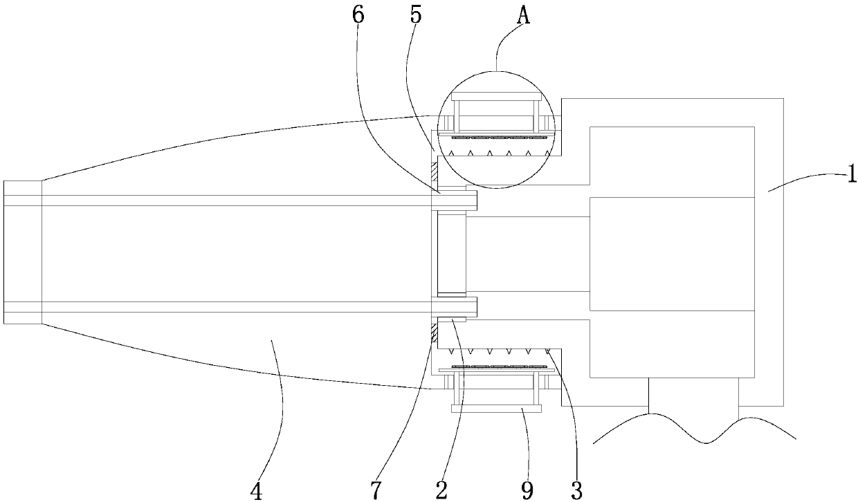
[0025] Such as Figure 1-3 As shown, a fuel nozzle assembly with a manifold includes a manifold 1, a fixed sleeve 2, a bearing tooth 3, a nozzle 4, a groove 5, a boss post 6, a buffer washer 7, a brazing hole 8, and a limit device 9, The number of fixed sleeves 2 is two, and the two fixed sleeves 2 are symmetrically arranged on the top and bottom of the left side of the main pipe 1. The number of load-bearing teeth 3 is twelve, and the load-bearing teeth 3 are symmetrically fixedly connected to the top and bottom of the main pipe 1 respectively. On the left side of the bottom, the nozzle 4 is set on the left side of the main pipe 1, the groove 5 is opened in the middle of the right side of the nozzle 4, the number of the bosses 6 is two, and the two bosses 6 are symmetrically arranged on the left side of the groove 5 inner cavity At the top and bottom of the side, the buffer gasket 7 is arranged in the middle of the left side of the inner cavity of the groove 5, and the number...

Embodiment 2

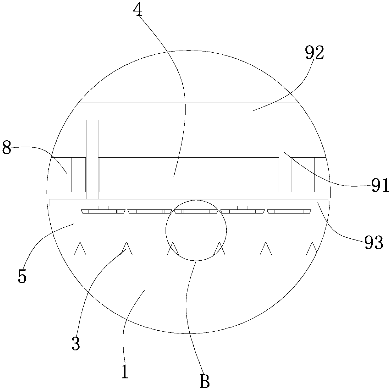
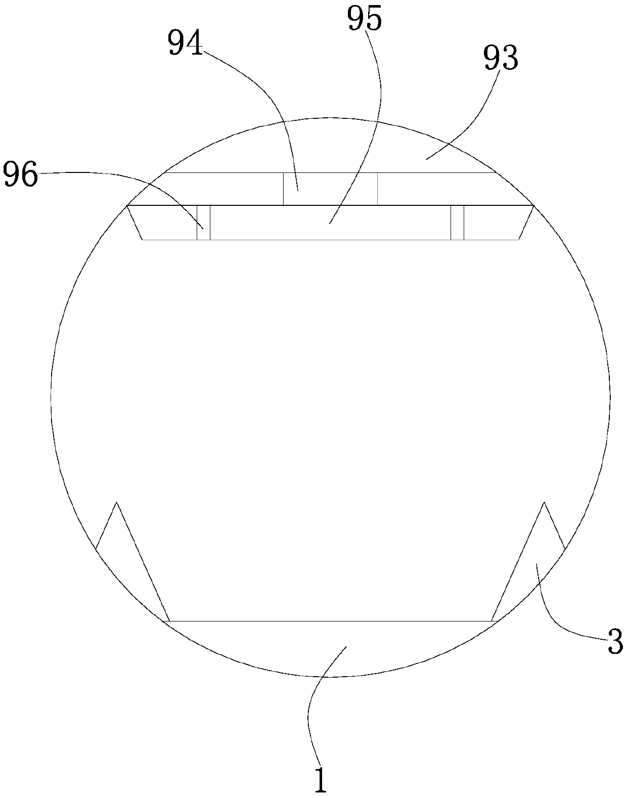
[0027] On the basis of Embodiment 1, the limiting device 9 includes a connecting rod 91, a pressing plate 92, a bearing plate 93, a support rod 94, a limiting plate 95, and a through hole 96. The number of connecting rods 91 is two, two The connecting rods 91 are symmetrically arranged on the left and right sides between the pressing plate 92 and the bearing plate 93, the number of the supporting rods 94 is five, and the supporting rods 94 are uniformly fixedly connected to the side of the bearing plate 93 away from the connecting rod 91 , the number of limiting plates 95 is five, the limiting plate 95 is evenly arranged on one side of the bearing plate 93, the number of through holes 96 is ten, and the ten through holes 96 are respectively set on five limiting plates 95 left and right ends.

Embodiment 3

[0029] On the basis of Examples 1 and 2, the fixed sleeve 2 runs through the wall on the left side of the main pipe 1 and extends to the inside of the main pipe 1. The fixed sleeve 2 is closely attached to the wall of the main pipe 1 and is fixedly connected. It is arranged at one end away from the main pipe 1.


PUM


Abstract

The invention discloses a fuel nozzle assembly with a main pipe and a brazing method, and relates to the technical field of fuel nozzles. The fuel nozzle assembly with the main pipe comprises the mainpipe, fixing sleeves, force-bearing teeth, a nozzle, a groove, boss columns, buffer washers, drill injection holes and limiting devices, wherein the number of the fixing sleeves is two, and the two fixing sleeves are symmetrically arranged at the top and the bottom of the left side of the main pipe; the number of the force-bearing teeth is twelve, and the twelve force-bearing teeth are symmetrically and fixedly connected to the left sides of the top and the bottom of the main pipe respectively; the nozzle is arranged on the left side of the main pipe; the groove is formed in the middle of theright side of the nozzle; the number of the boss columns is two, and the two boss columns are symmetrically arranged at the top and the bottom of the left side of an inner cavity of the groove; and the buffer washers are arranged in the middle of the left side of the inner cavity of the groove. According to the fuel nozzle assembly with the main pipe, the brazing joint structure is optimized, thebrazing feasibility of the assembly is improved, the sealing property between the main pipe and a joint is ensured, and oil in main and auxiliary oil paths is prevented from being mixed together.

Description

technical field [0001] The invention relates to the technical field of fuel nozzles, in particular to a fuel nozzle assembly with a manifold and a brazing method. Background technique [0002] The fuel nozzle is a key component of an aero-engine. In order to meet the needs of variable loads of thermal equipment, a dual oil circuit centrifugal nozzle has been developed. In order to ensure the quality of components, vacuum brazing is often used to connect with other parts. Therefore, the seal between the main and auxiliary oil circuits is very important. At present, most of the solutions are to process the main and auxiliary oil circuits on the same housing, so as to directly ensure the sealing between the main and auxiliary oil circuits. However, there are some specific structures, and the two need to be processed separately, and subsequent processing is used to ensure that the two do not bleed oil. The connection between the existing main pipe and the fuel nozzle, after br...

Claims


Application Information

Patent Timeline
Patent Type & Authority Applications(China)
IPC IPC(8): F02C7/22F23R3/28B23K3/047B23K3/06B23K3/08
CPCF02C7/222F02C7/22F23R3/28B23K3/047B23K3/0607B23K3/085
Inventor 彭建科马春力李虎平苏展杨冰
Owner 西安成立航空制造有限公司
Why Eureka
Try Eureka