Self-seal heat-preservation-layer-free outer side cavity structure for water pan and air conditioner with self-seal heat-preservation-layer-free outer side cavity structure

A technology of sealing structure and water receiving tray, applied in the application, household heating, household heating and other directions, can solve the problems of unfavorable branch operation, high cost, increase assembly parts and other problems, and achieve the effect of avoiding condensation and dripping.

Pending Publication Date: 2019-11-08
GREE ELECTRIC APPLIANCES INC
View PDF0 Cites 0 Cited by
  • Summary
  • Abstract
  • Description
  • Claims
  • Application Information

AI Technical Summary

Problems solved by technology

[0002] In the current conventional water tray 3 parts, such as figure 1 As shown, the surface of the water tray is insulated by the sponge 12 and the foam to solve the problem of condensation water on the surface of the material of the water tray. In this process, two or even three parts are involved in the foam to solve this problem, and assembly parts are added. and require production man-hours
This form of assembly is not conducive to branch operation, and the cost is also high

Method used


Image

  • Self-seal heat-preservation-layer-free outer side cavity structure for water pan and air conditioner with self-seal heat-preservation-layer-free outer side cavity structure
  • Self-seal heat-preservation-layer-free outer side cavity structure for water pan and air conditioner with self-seal heat-preservation-layer-free outer side cavity structure
  • Self-seal heat-preservation-layer-free outer side cavity structure for water pan and air conditioner with self-seal heat-preservation-layer-free outer side cavity structure

Examples


Embodiment 1

[0026] The outer cavity structure of the self-sealing insulation-free layer used for the water tray includes the matching indoor unit shell 4 and the water tray 3 for receiving condensed water on the evaporator, and the surface of the matching indoor unit shell 4 and the water tray 3 A cavity sealing structure is provided between the outer surfaces. A casing cover 5 is installed on the casing 4 of the supporting indoor unit through fasteners, a sealing structure is provided between the casing cover 5 and the water receiving tray 3, and the casing cover 5 and the sealing structure are connected along the water receiving tray. 3. The surface extends in the front-back direction or in the left-right direction to form the sealed structure of the cavity.

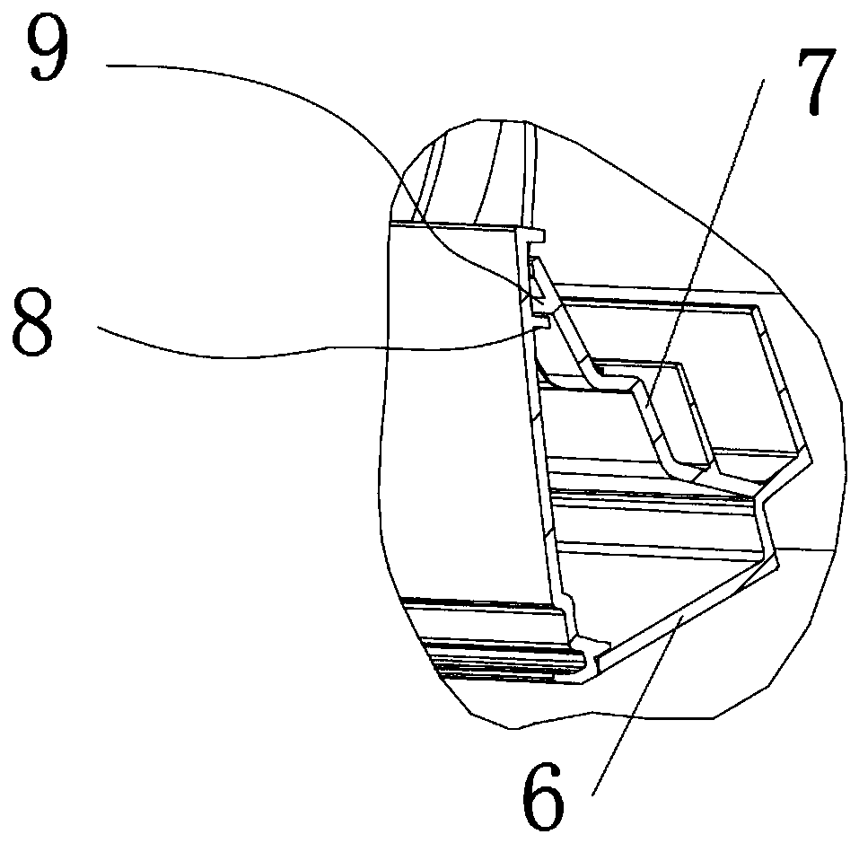
[0027] The water tray 3 includes a base 6 and a support plate 7 , and an angle is formed between the base 6 and the support plate 7 .

[0028] The sealing structure includes a first groove 8 extending horizontally on the support ...

Embodiment 2

[0030] The difference between this embodiment and Embodiment 1 is that the sealing structure includes a third convex groove extending horizontally on the support plate 7, and the inner wall of the housing cover plate 5 is provided with a fourth convex groove extending horizontally. , the third protruding groove and the fourth protruding corrugation, the third protruding groove and the fourth protruding corrugation are not marked in the figure, can refer to the first embodiment, the lower end of the shell cover plate 5 is provided with the first horizontally extending Two corrugations 10 , the second corrugation 10 is pressed against the free end surface of the support plate 7 .

[0031] Implementation three

[0032] The difference between this embodiment and Embodiment 1 is that the sealing structure is to realize the self-sealing of the parts on the outer side of the water tray 3 through the design of the injection mold and the injection molding machine tool with a gas-assist...

Embodiment 5

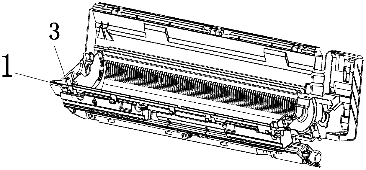
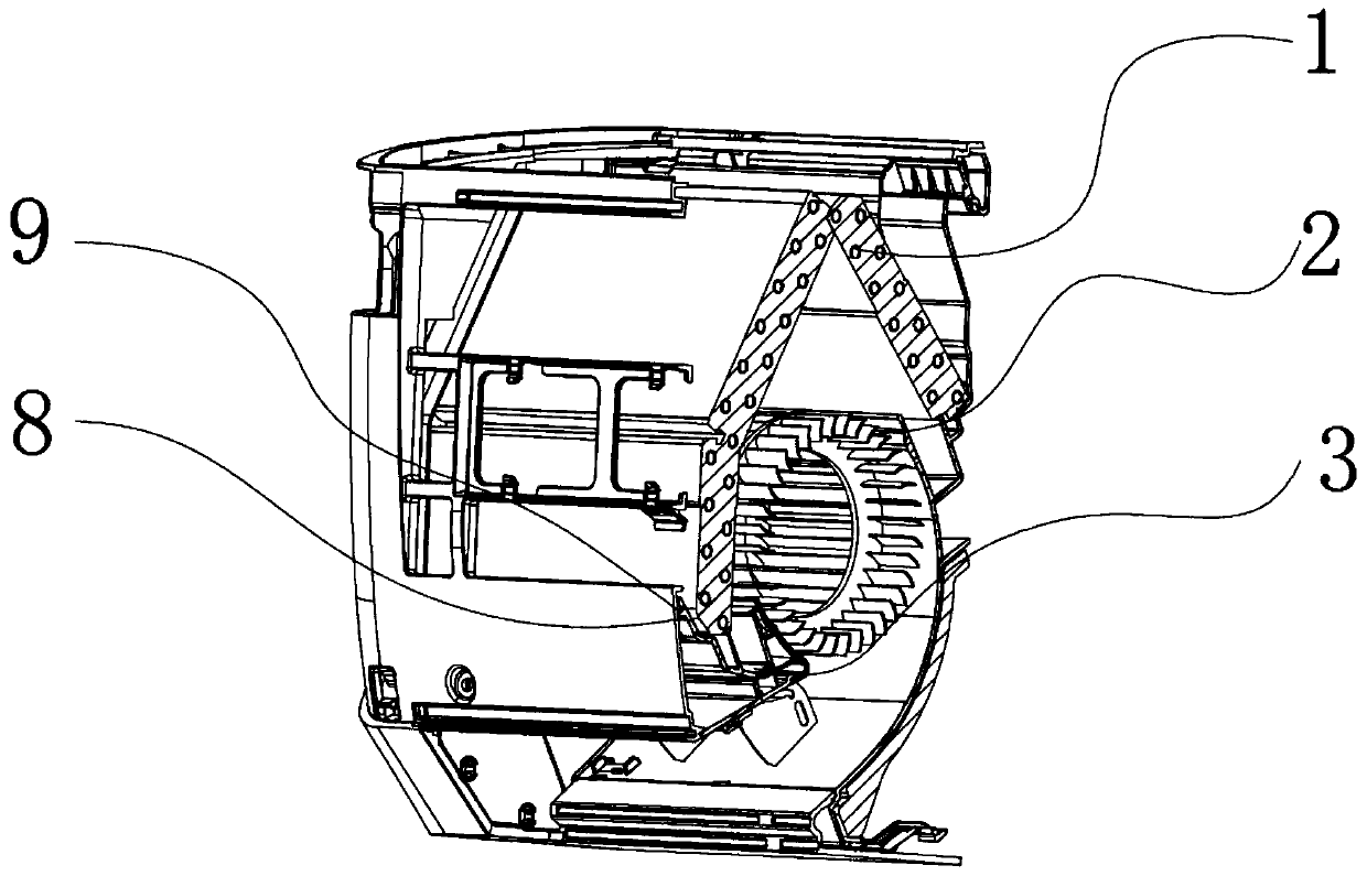
[0036] Another technical solution of the present invention is achieved as follows: the air conditioner includes an indoor unit, the indoor unit is provided with an indoor evaporator component 1 and an internal unit cross-flow fan 2, and the indoor unit housing 4 is provided with any of the above-mentioned The outer cavity structure of the self-sealing insulation-free layer used for the water receiving tray 3.

[0037] After the patent seals the outer surface of the water tray 3 with a full enclosure, it can prevent the flowing air containing a large amount of water from entering the outer surface of the water tray 3, thereby avoiding the need to cancel foam and sponge insulation on the outer surface of the water tray 3. After layering, the air in the cavity formed between the outside of the water receiving tray 3 and the inner machine casing continues to circulate, and when the circulating air contains moisture, when the air contacts the outside of the water receiving tray 3, t...


PUM


Abstract

The invention provides a self-seal heat-preservation-layer-free outer side cavity structure for a water pan and an air conditioner with the self-seal heat-preservation-layer-free outer side cavity structure. The self-seal heat-preservation-layer-free outer side cavity structure for the water pan comprises a matched indoor unit shell and a water pan for bearing condensate water on an evaporator. Acavity seal structure is arranged between the surface of the matched indoor unit shell and the outer side surface of the water pan. The air conditioner comprises an indoor unit, an indoor evaporator component and an indoor unit cross-flow fan are arranged in the indoor unit, and the self-seal heat-preservation-layer-free outer side cavity structure for the water pan is arranged in the indoor unitshell. The self-seal heat-preservation-layer-free outer side cavity structure replaces the heat preservation function of original foam and sponge, the work of sponge or foam part pasting during air conditioner indoor unit water pan production is eliminated, and the assembling burden of operators is relieved.

Description

technical field [0001] The invention relates to the technical field of air conditioners, in particular to a self-sealing insulation-free outer cavity structure for a water tray and an air conditioner thereof. Background technique [0002] In the current conventional water tray 3 parts, such as figure 1 As shown, the surface of the water tray is insulated by the sponge 12 and the foam to solve the problem of condensation water on the surface of the material of the water tray. In this process, two or even three parts are involved in the foam to solve this problem, and assembly parts are added. And need to consume production man-hour. This form of assembly is not conducive to the operation of the branch factory, and the cost is also high. Contents of the invention [0003] The invention proposes a self-sealing insulation-free outer cavity structure for the water tray and its air conditioner, which replaces the heat preservation effect of the original foam and sponge, and el...

Claims


Application Information

Patent Timeline
Patent Type & Authority Applications(China)
IPC IPC(8): F24F13/22
CPCF24F13/222
Inventor 徐兴东常豪杰黄智伟张煜晨
Owner GREE ELECTRIC APPLIANCES INC
Why Eureka
Try Eureka