Electronic product high-temperature sintering furnace

A technology for high-temperature sintering and electronic products, which is applied in the direction of electric furnace heating, furnace, furnace components, etc. It can solve the problems of long shutdown time of sintering furnace, affecting the sintering efficiency of electronic components and electronic powder materials, and high cost of silicon-molybdenum rods.

Inactive Publication Date: 2019-11-08
SUZHOU HUIKE EQUIP CO LTD
View PDF3 Cites 6 Cited by
  • Summary
  • Abstract
  • Description
  • Claims
  • Application Information

AI Technical Summary

Problems solved by technology

Although this structural arrangement can meet the requirements of use, when the silicon-molybdenum rods need to be replaced after a period of use such as one to two years, the silicon-molybdenum rods can only be taken out by removing the aforementioned furnace roof bricks. When the silicon-molybdenum rods are returned, the furnace roof bricks need to be rebuilt. Therefore, not only the engineering volume of replacing the silicon-molybdenum rods is large, but the cost of replacing the silicon-molybdenum rods is high. Therefore, there is a risk of affecting the overall structure of the furnace body, and because the replacement of silicon-molybdenum rods takes a long time and is treated and handled as a project, the si...

Method used


Image

  • Electronic product high-temperature sintering furnace
  • Electronic product high-temperature sintering furnace

Examples


Embodiment Construction

[0022] In order to understand the technical essence and beneficial effects of the present invention more clearly, the applicant will describe in detail the following examples, but the descriptions of the examples are not intended to limit the solutions of the present invention. Equivalent transformations that are only formal but not substantive should be regarded as the scope of the technical solution of the present invention.

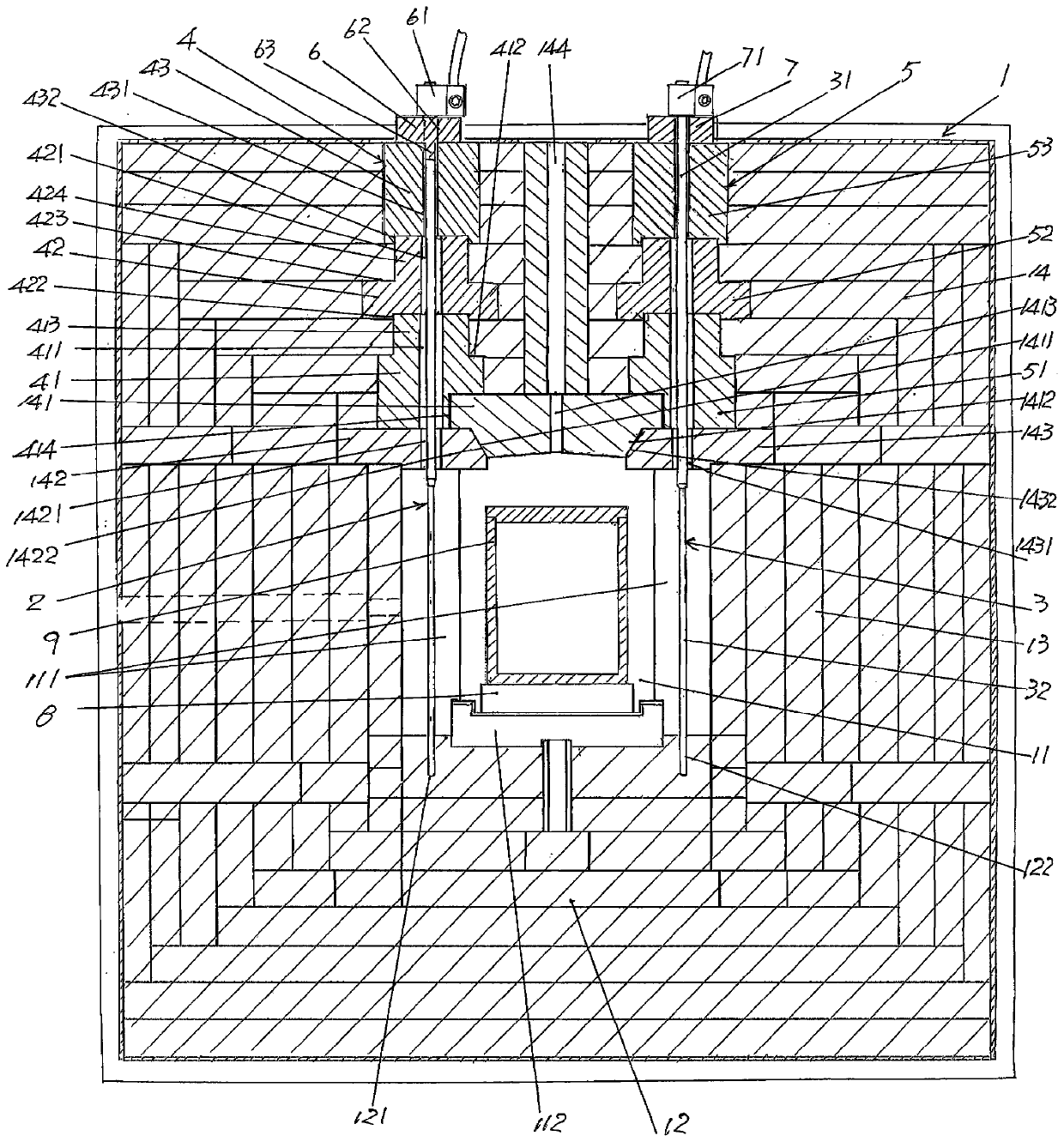
[0023] In the following descriptions, all concepts related to directionality or orientation of up, down, left, right, front and back are based on figure 1 The current position is a reference, so it cannot be understood as a special limitation on the technical solution provided by the present invention.

[0024] See figure 1 , shows a furnace body 1 that belongs to the category of tunnel kiln and has a length of more than ten meters or even tens of meters or even longer. The front end of the furnace runs through to a furnace 11 at the rear end. The fu...


PUM


Abstract

The invention provides an electronic product high-temperature sintering furnace and belongs to the technical field of electronic kiln furnace facilities. The electronic product high-temperature sintering furnace comprises a furnace body, the center of the furnace body is provided with a furnace cavity, silicon molybdenum bar left heating units and silicon molybdenum bar right heating units are distributed to the rear end of the furnace cavity from the front end of the furnace cavity at the positions corresponding to the left side and the right side of the furnace cavity, the electronic producthigh-temperature sintering furnace is characterized by further comprising left plug brick mechanisms, right plug brick mechanisms, left extraction release bricks and right extraction release bricks,the left plug brick mechanisms and the right plug brick mechanisms are built inside furnace top bricks at the positions corresponding to the silicon molybdenum bar left heating units and the silicon molybdenum bar right heating units, the left extraction release bricks and the right extraction release bricks are located at the top of the furnace body, the lower ends of the silicon molybdenum bar left heating units penetrate through the left plug brick mechanisms and stretch to the bottom of the furnace cavity, the upper ends of the silicon molybdenum bar left heating units penetrate through the left extraction release bricks from bottom to top and poke out of the upper surfaces of the left extraction release bricks, the lower ends of the silicon molybdenum bar right heating units penetratethrough the right plug brick mechanisms and stretch to the bottom of the furnace cavity, and the upper ends of the silicon molybdenum bar right heating units penetrate through the right extraction release bricks from bottom to top and poke out of the upper surfaces of the right extraction release bricks. By means of the electronic product high-temperature sintering furnace, the engineering cost of silicon molybdenum bar replacement is reduced, and the sintering efficiency is improved.

Description

technical field [0001] The invention belongs to the technical field of electronic kiln facilities, and in particular relates to a high-temperature sintering furnace for electronic products. Background technique [0002] The aforementioned electronic products mainly include various electronic components and electronic powder materials. As known in the industry, no matter it is used for sintering various electronic components, or for sintering various common and special and high-end electronic powder materials, the structure of the furnace body and the heating components and their setting methods are systemic. its very important component. This can be confirmed by the "hearth structure of battery material sintering furnace" recommended by Chinese patent CN105783517A and the "hearth heating device of MIN sintering furnace" provided by CN204934610U. [0003] Furthermore, as known in the industry, the sintering temperature of some electronic materials such as alumina substrates...

Claims


Application Information

Patent Timeline
IPC IPC(8): F27D1/02F27D1/04F27D11/02
CPCF27D1/02F27D1/04F27D11/02
Inventor 陈龙豪张文俊钱虞清戴羽
Owner SUZHOU HUIKE EQUIP CO LTD
Why Eureka
Try Eureka