

Wheel rim driving device
A wheel-side drive and wheel-hub technology, which is applied to power units, wheel-fixing devices, measuring devices, etc., can solve problems such as unreliability, easy torque slippage, complex structure, etc., and achieves simple structure, good stress condition, and reduced slippage. effect of risk
- Summary
- Abstract
- Description
- Claims
- Application Information
AI Technical Summary
Problems solved by technology
Method used
Image

Examples
Embodiment 1
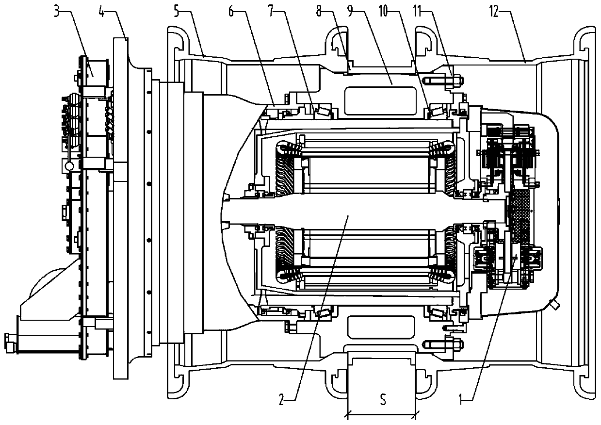
[0033] The wheel edge driving device of the present embodiment is as figure 2 As shown, the wheel frame 4 is fixed on the car body, and the traction motor 2 installed on its outside determines the axis of rotation. The inner output end of the motor 2 is connected to the torque tube 6 supported in the wheel frame 4 through a gear device 3. Therefore, the high-speed torque output by the traction motor 2 can be transmitted to the torque tube 6 after the gear device 3 reduces the speed and increases the torque. The flange edge of the outer end of the torque tube 6 is fixedly connected with the inner end of the wheel hub 9 outside the motor housing through the inner and outer bearings 7 and 10, and the outer end of the motor 2 is connected with the wheel frame 4 through the braking device 1, and It is connected with the outer end of the hub 9 to form an outer sealing device. The braking device 1 is composed of a brake caliper and a brake disc, wherein the brake caliper is connecte...
Embodiment 2
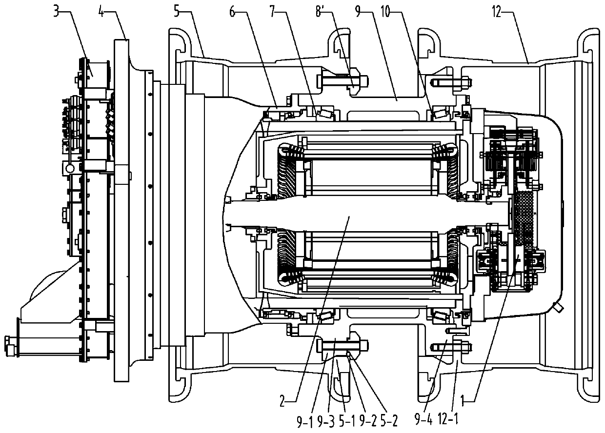
[0041] The wheel edge driving device of the present embodiment is as image 3 As shown, the basic structure is the same as that of Embodiment 1, except that an inner retaining wall 5-2 with perforations extends near the outer end of the inner rim 5 toward the axis of rotation, and the inner end of the hub 9 has a flange flange 9-2 ’, the outer end surface of the flange flange 9-2’ fits with the inner end surface of the inner retaining wall 5-2, and a fastening structure is formed by passing through bolts and nuts. Near the inner end of the outer rim 12 extends toward the axis of rotation a perforated inner retaining ring 12-2 that abuts against the outer end surface of the hub 9 and has a threaded hole, and the bolt passes through the perforation of the inner retaining ring 12-2 and the perforation of the outer sealing device at the same time , screwed into the threaded holes on the periphery of the outer end surface of the hub 9 to form a pressing and fastening structure, and...
Embodiment 3
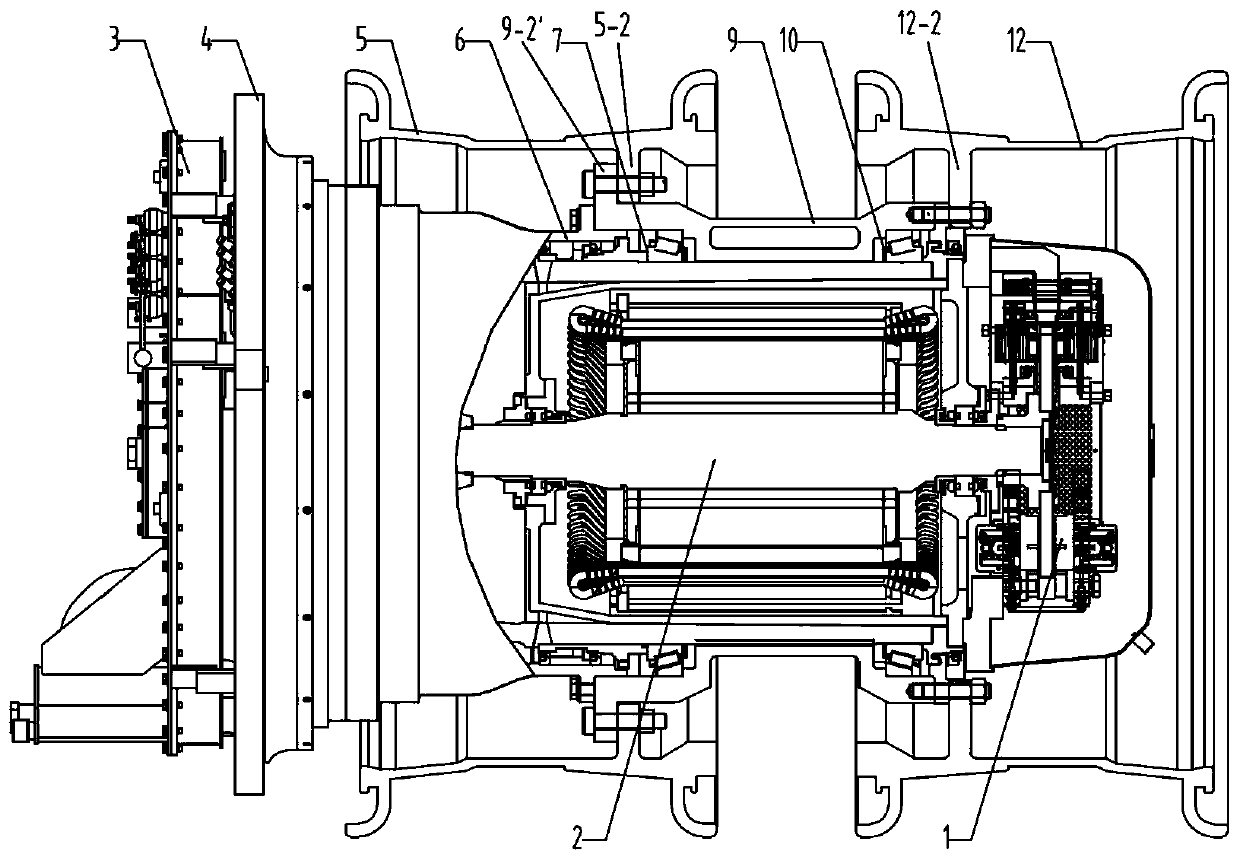
[0047] The wheel edge driving device of the present embodiment is as Figure 4 As shown, the basic structure is the same as that of Embodiment 1, and the outer end of the inner rim 5 has a wedge-shaped closing 5-1, and the inner end of the hub 9 has a radially extended edge 9-3 on one side to form a matching wedge-shaped closing 5-1. Wedge-shaped seam 9-1, the inner end of its outer rim 12 has a wedge-shaped closing 12-1, and the outer end of the wheel hub 9 is equipped with a beveled wedge ring 11', which has a wedge shape with the inner end of the outer rim 12. The wedge-shaped inclined surface matched with the mouth 12-1; the significant difference is that the outer end of the beveled wedge ring 11' has a reduced-diameter stop 11-2 that presses the outer end of the hub 9, and the inner end of the bevel extends out to be inserted into the hub 9 and the radially spaced wedge plugs 11-1 of the outer rim 12. The wedge-shaped notch 9-1 at the inner end of the hub 9 and the wedg...
PUM
 Abstract
Description
Claims
Application Information