Multistage yield stability resistance bearing support
A load-stabilizing force and sleeve technology, applied to building components, earthquake resistance, building types, etc., can solve problems such as insufficient ductility of metal dampers, and achieve the effects of enhancing energy consumption capacity of supports, increasing ductility, and large-tonnage design
- Summary
- Abstract
- Description
- Claims
- Application Information
AI Technical Summary
Problems solved by technology
Method used
Image
Examples
Embodiment 1
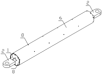
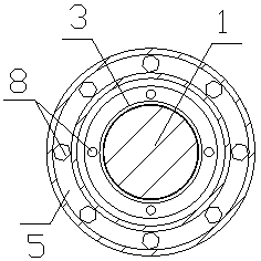
[0057] see Figure 1 to Figure 22 , the multi-stage yielding anti-stabilization brace includes two rigid mandrels (1), two connection nodes (2), two inner anti-stabilization sleeves (5) and one outer anti-stabilization sleeve (6), It is characterized by:
[0058]1) The coaxial lines of the two rigid mandrels (1) are respectively installed in the two inner anti-stabilization sleeves (5), and the two anti-stability sleeves (5) are installed in the outer anti-stability sleeve (6), The inner ends of the two inner anti-stabilizing sleeves (5) are connected by a torsion limiting device, and the outer ends of the two rigid mandrels (1) are each fixedly connected to a connection node (2);
[0059] 2) The rigid mandrel (1) is equipped with multiple yield energy dissipation sections (3), and one end of each yield energy dissipation section (3) is connected to the rigid mandrel (1) by an energy dissipation section (4) ), and the other end is fixedly connected with the inner anti-stabil...
Embodiment 2
[0060] Embodiment 2: This embodiment is basically the same as Embodiment 1, and the special features are as follows:
[0061] There is a gap between the rigid mandrel (1) and the yield energy-dissipating section (3), which is filled with non-adhesive material to reduce friction; a longitudinal positioning device and a torsion limiting device are provided to ensure that the rigid mandrel (1) ) without offset and torsion; the inner and outer anti-stability sleeves (5, 6) are circular, or square, or regular polygonal in appearance.
[0062] By arranging yield energy dissipation sections (3) with different yield points or lengths, multi-stage yield energy dissipation is realized.
[0063] The longitudinal positioning device includes a limit groove longitudinal restraint plate (9) and a wear-resistant rolling body (10), and the wear-resistant rolling body (10) is placed in the limit groove of the limit groove longitudinal restraint plate (9) to form a longitudinal positioning devic...
Embodiment 3
[0069] Such as Figure 1 to Figure 22 As shown, the multi-stage yielding anti-stabilization brace includes a rigid mandrel (1), a longitudinal positioning device, a torsion limiting device, a multi-stage yielding energy dissipation section (3), energy dissipation section connecting parts (4), inner Anti-stability sleeve (5), outer anti-stability sleeve (6), sleeve connection part (7), connection node (2), occlusal-bolt connection, torsion limit installation device (16).
[0070] The connecting node (2) is connected to the rigid mandrel (1); the longitudinal positioning device is connected to the sleeve connecting part (7) through a bite-bolt connection; both ends of the torsion limiting device are connected to the sleeve connecting part (7) ) is connected by bolts; the connecting part (4) of the energy dissipation section is placed coaxially with the rigid mandrel (1) and fixedly connected by welding; the yield energy dissipation section (3) is coaxial with the rigid mandrel (...
PUM
 Abstract
Description
Claims
Application Information
 - R&D
- Intellectual Property
- Life Sciences
- Materials
- Tech Scout
- Unparalleled Data Quality
- Higher Quality Content
- 60% Fewer Hallucinations
Browse by: Latest US Patents, China's latest patents, Technical Efficacy Thesaurus, Application Domain, Technology Topic, Popular Technical Reports.
© 2025 PatSnap. All rights reserved.Legal|Privacy policy|Modern Slavery Act Transparency Statement|Sitemap|About US| Contact US: help@patsnap.com


