Layer-by-layer acidification and stratified water injection method

A layer-by-layer water injection and layer-by-layer technology, which is applied to earthwork drilling, wellbore/well valve devices, cleaning tools, etc., can solve the problems of increased material costs, long cycle, and acid liquid cannot be discharged on site, and achieve saving the effect of time

Active Publication Date: 2019-11-12
CHINA PETROLEUM & CHEM CORP +1
View PDF4 Cites 1 Cited by
  • Summary
  • Abstract
  • Description
  • Claims
  • Application Information

AI Technical Summary

Problems solved by technology

[0005] The traditional acidizing plugging removal process mainly has the following problems: (1) Due to the pressure relief or liquid drainage after acidizing, the oil layer may be excited, causing particle migration and causing damage to the reservoir, and there is a certain risk; (2) After acidizing plugging removal, it is necessary to Long-term flowback treatment takes up a long time in the well; (3) There are many construction procedures, long periods, and many tools are used, which increases the operating cost; (4) During the swabbing and drainage process, in order to prevent the coating damage of the paint tubing under the screen, it is necessary to A new set of ordinary oil pipes is used for acidification and liquid drainage construction, which increases the cost of materials; (5) The acid liquid discharged from the return cannot be discharged on site, and needs to be transported to a designated place by special vehicles for treatment, which increases subsequent treatment costs

Method used


Image

  • Layer-by-layer acidification and stratified water injection method
  • Layer-by-layer acidification and stratified water injection method
  • Layer-by-layer acidification and stratified water injection method

Examples


Embodiment Construction

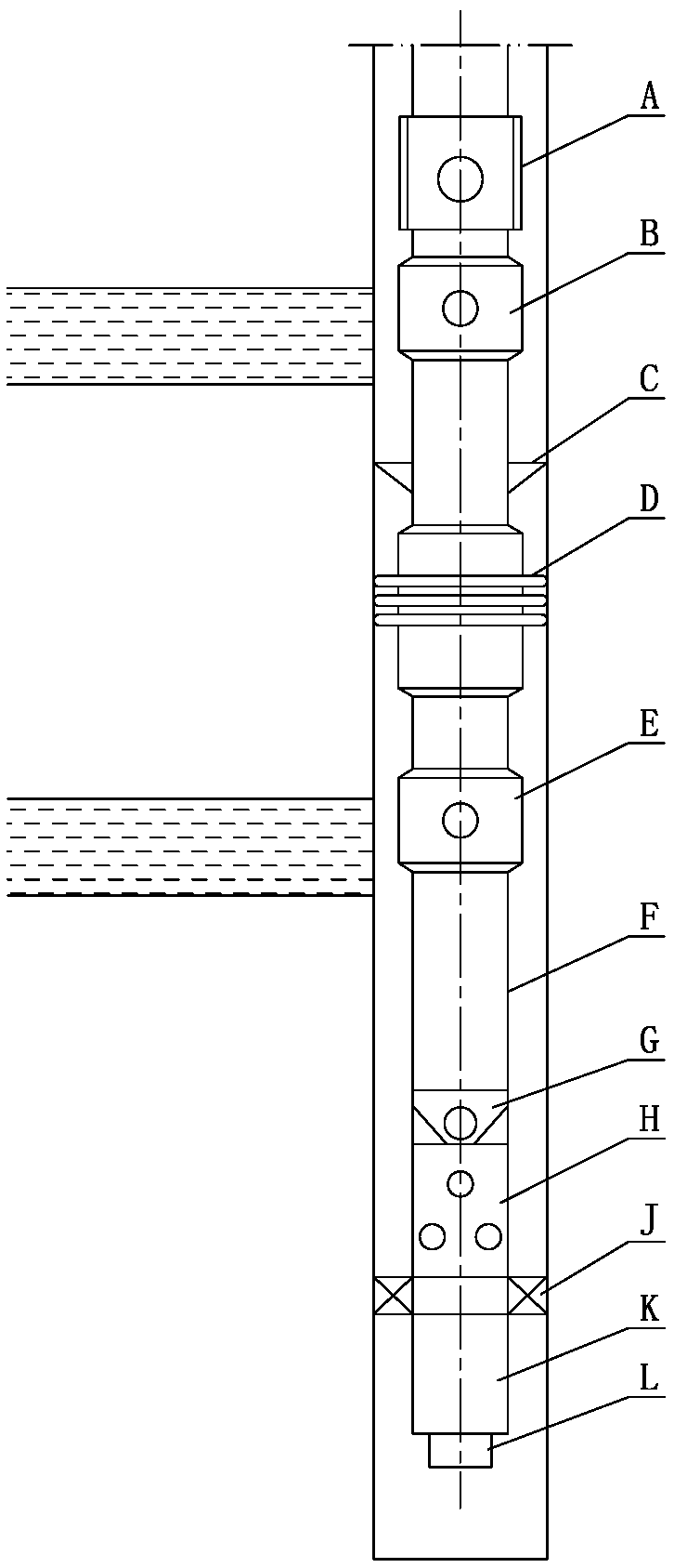
[0026] The method for layer-by-layer acidification and layered water injection of the present invention comprises the following steps in turn: (1) down the acid injection integrated pipe string into the casing, the acid injection integrated pipe string is as follows: figure 1 As shown, from top to bottom, it includes switch valve A, upper eccentric water distributor B, packer D, lower eccentric water distributor E, intermediate oil pipe F, acidizing check valve G, screen pipe H, paint oil pipe K and plug L; a centralizer C can be installed above the packer D to make the expansion of the rubber cartridge more uniform when the packer D is set, and a tubing holder J can be installed between the screen H and the paint tubing K.

[0027] ⑵According to the different clogging conditions of the upper and lower water injection layers, the pretreatment liquid is configured, and the respective acid liquids are configured.

[0028] (3) Start the cement truck for positive circulation, that...


PUM


Abstract

The invention relates to a layer-by-layer acidification and stratified water injection method. The method comprises the following steps in sequence that an acid injection integrated tubular column isput into a casing, pretreatment fluid and respective acid liquor of upper and lower strata are prepared, after the positive circulation of fluid is normal, the positive substitution of the pretreatment fluid is carried out, a 31mm steel ball is dropped into a acidizing single flow valve, and a cement truck forward presses to set a packer; the cement truck continues to boost the pressure, shears ashear pin of an inner sleeve ball seat, and the inner sleeve ball seat falls into an inner coated tubing; lower acid liquor is then sent down a well, flows from a screen and enters into a lower waterinjection layer; another a 48mm soluble ball is dropped into a switch valve for setting, the pretreatment fluid is forward pressed to open an acid liquor channel of a barrel wall of the switch valve,and then upper acid liquor is injected into an upper water injection layer; then the well is closed, and two strata continue to acidify; after the acidification reaction is complete, and the soluble ball is dissolved; and a 40mm sealing steel ball is put in, and water is injected normally after tests of throwing and retrieving and sealing are qualified. According to the method, only one trip is needed, the operation cost is low, a well occupancy period is short, the development cost of an oilfield is reduced, and the environmental benefit is good.

Description

technical field [0001] The invention relates to a layered water injection method, in particular to a layer-by-layer acidification layered water injection method, which belongs to the technical field of water injection well acidification technology. Background technique [0002] After a period of development of water injection wells, especially in the late stage of oilfield development, the water injection pressure of most water injection wells will increase greatly, and it will show a trend of increasing year by year, resulting in less and less water injection, which will affect the water injection development effect. Severe impact, ultimately greatly reducing oil field production. [0003] Acidizing is a measure to remove plugging and increase injection that is often taken on the formation. It uses the chemical dissolution of acid liquid and the hydraulic action when squeezing acid into the formation to dissolve formation blockages and some formation minerals, expand, exten...

Claims


Application Information

Patent Timeline
IPC IPC(8): E21B37/06E21B34/14
CPCE21B34/14E21B37/06
Inventor 熊涛聂厚文赵智超程浩
Owner CHINA PETROLEUM & CHEM CORP
Why Eureka
Try Eureka