
Carbon fiber storage circulating fan

A circulating fan and carbon fiber technology, which is applied to mechanical equipment, machines/engines, liquid fuel engines, etc., can solve the problem that the storage circulating fan is difficult to meet the requirements of use, and achieve simple and reasonable structure, reduce power consumption, and reduce rotational vibration. Effect

Pending Publication Date: 2019-11-12
洛阳北玻三元流风机技术有限公司
View PDF0 Cites 0 Cited by
  • Summary
  • Abstract
  • Description
  • Claims
  • Application Information

AI Technical Summary

Problems solved by technology

[0003] In order to solve the above-mentioned problem that the existing storage circulation fan is difficult to meet the use requirements, the present invention provides a carbon fiber storage circulation fan

Method used


Image

  • Carbon fiber storage circulating fan
  • Carbon fiber storage circulating fan
  • Carbon fiber storage circulating fan

Examples


specific Embodiment approach

[0023] Referring to the accompanying drawings, the specific implementation is as follows:

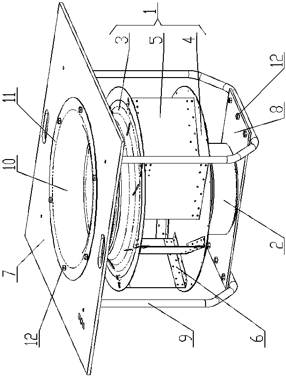
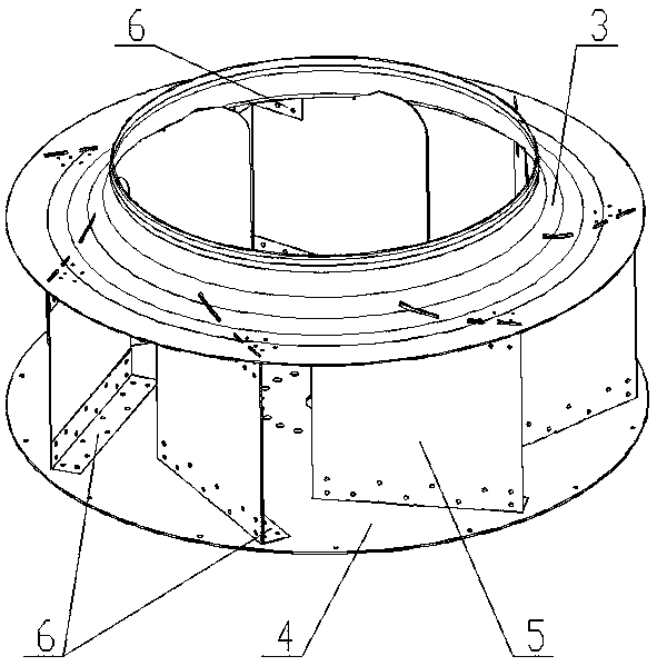
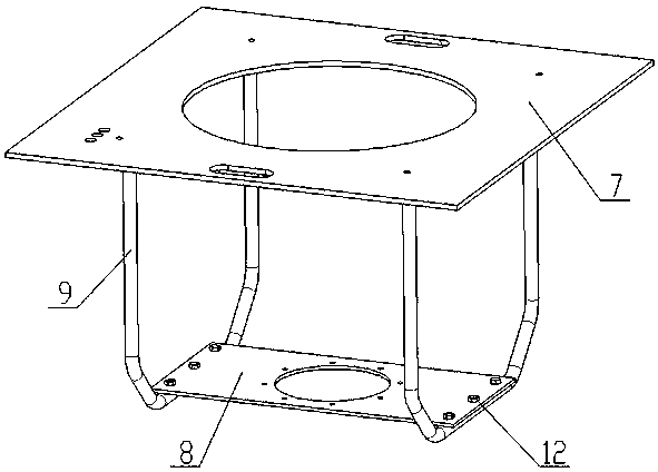
[0024] Such as figure 1 As shown, a carbon fiber storage circulating fan includes a fan impeller 1, a motor 2 and a fan mounting frame, such as figure 2 As shown, the fan impeller 1 includes a front disk 3, a rear disk 4 and a plurality of blades 5, and the plurality of blades 5 are located between the front disk 3 and the rear disk 4 and are arranged at uniform intervals along the circumference of the fan impeller 1. The front disk 3 , the rear plate 4 and the blade 5 are respectively formed by laminating multiple layers of carbon fiber materials along the thickness direction. The carbon fiber material is one of carbon fiber prepreg, carbon fiber dry cloth, carbon fiber powder, and carbon fiber unidirectional yarn. Carbon fiber angle steel 6 is provided on both sides of the connection between the disk 3 and the rear disk 4, one side of the carbon fiber angle steel 6 is attached to th...


PUM


Abstract

The invention provides a carbon fiber storage circulating fan which comprises a fan impeller, a motor and a fan mounting rack. The fan impeller comprises a front disk, a rear disk and a plurality of blades; the front disk, the rear disk and the blades are correspondingly formed by laminating multiple layers of carbon fiber materials; carbon fiber angle iron is arranged on the edges of two sides ofeach blade; one side surface of each carbon fiber angle iron is arranged on the corresponding blade in a laminating manner; the other side surface of each carbon fiber angle iron is arranged on the surface of the front disk or the rear disk in a laminating manner; the fan mounting rack comprises a carbon fiber top plate mounted on the top surface of a wall; a carbon fiber bottom plate is arrangedbelow the carbon fiber top plate; the motor is mounted on the upper surface of the carbon fiber bottom plate; the fan impeller is mounted at the top end of the motor; an air inlet is formed in a through hole in the carbon fiber top plate; the two axial ends of the air inlet are flared; the bottom end of the air inlet extends to the lower side of the front disk from a through hole in the front disk to facilitate air flowing into a part between the front disk and the rear disk; U-shaped carbon fiber rods are correspondingly arranged on two sides of the fan impeller; and the carbon fiber bottomplate is supported and fixed through the cooperation of straight bars at bending parts of the U-shaped carbon fiber rods.

Description

technical field [0001] The invention relates to the field of storage circulation fans, in particular to a carbon fiber storage circulation fan. Background technique [0002] Warehousing circulation fans are generally installed on the roof of warehouses and other locations, and are used to deliver external air to warehouses and other buildings that need to be ventilated. The material of the existing storage circulation fan is mainly metal, and there are the following problems: first, the impeller made of metal has poor corrosion resistance and is easily corroded, which seriously affects its service life; second, the air intake effect of the existing fan is poor , In order to ensure the air intake, the rotation speed of the fan must be high, which increases the energy consumption and reduces the ventilation efficiency. Third, the existing metal fan has a relatively large weight, and the fixing between the blades and the wheel is more demanding, and the connection structure be...

Claims


Application Information

Patent Timeline
Patent Type & Authority Applications(China)
IPC IPC(8): F04D25/08F04D29/02F04D29/28F04D29/30
CPCF04D25/08F04D29/281F04D29/30F04D29/023
Inventor 李建森彭焕朱博炜高坦克
Owner 洛阳北玻三元流风机技术有限公司
Learn More