A multi-parameter optical fiber sensing instrument and sensing method based on multi-core optical fiber
A multi-core optical fiber and optical fiber sensing technology, which is applied in the direction of converting sensor output, using optical devices to transmit sensing components, instruments, etc., can solve problems such as difficult to meet the needs of use, achieve convenient connection settings, wide application scenarios, and reduce fiber optics. Effect of number of cores
- Summary
- Abstract
- Description
- Claims
- Application Information
AI Technical Summary
Problems solved by technology
Method used
Image
Examples
Embodiment 1
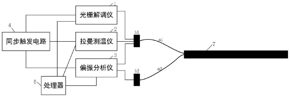
[0055] Embodiments of the present invention provide a multi-variable amount fiber sensing instrument based on multi-core fibers, such as figure 1 As shown, a grating demodulator 1, a Raman thermometer 2, a polarization analyzer 3, a synchronous trigger circuit 4, and a processor 5, a grating demodulator 1, alam thermometer 2, and said The polarization analyzer 3 is in parallel between the three detecting devices; wherein the laminate thermometer 2 and the latter thermometer 2 and the tipped device 3 in the raster demodulator 1, the Raman Turbiner 2 and the polarization analyzer 3. The polarization analyzer 3 is multiplexed between the polarization analyzer 3, and the raster demodulator 1 and the remaining two devices are time division multiplexed.
[0056] refer to figure 1 The grating demodulator 1, the lamman thermometer 2 and the polarization analyzer 3 each pass through the first fiber interface B1, the front end of the first core A1 in the first core A1, and the polarization ...
Embodiment 2
[0095] Based on the above-described Embodiment 1, the embodiment of the present invention further integrates the portion of the raster demodulator 1, a Raman thermometer 2, and a polarization analyzer 3 in the three detection devices. Another multi-parameter fiber sensing instrument based on multi-core fiber, is more simple, less cost, less cost, and can be achieved with the structure in Example 1 compared to the multi-parameter fiber sensing instrument in Example 1. Function.
[0096] like Figure 9 As shown, the multi-parameter optical fiber sensing instrument provided by the embodiment of the present invention includes a Raman Light Source 601, a polarized light source 602, a fiber grating light source 603, a repository 604, a coupler 605, an annular device 606, a spectroscope 607, a 2Dolder 608, the polarization detector 609, the Stokes photodetector 610, the Anti-Stokes photodetector 611, the grating demodulation device 612, the acquisition card 613, the synchronous trigger ci...
Embodiment 3
[0109] The embodiment of the present invention provides a multi-parameter fiber sensing method based on a multi-core fiber, which can be accomplished using a multi-parameter fiber sensing instrument described in Example 1 or Embodiment 2. Prior to the introduction of the multi-parametric fiber sensing method of the embodiment of the present invention, the calculation formula and its derivation of each sensor technology are first introduced:
[0110] I. Ramano time domain reflection technology (Raman temperature measurement technology)
[0111] For Raman light time domain reflection technology, it is mainly responsive to temperature parameters. Antistoke scattered light is sensitive to temperature, its strength is modulated; and Stokes scattered light intensity has a certain relationship with temperature, but is small affected by temperature. Therefore, in the measurement, the intensity of Stokes scattered light and the anti-Stoke scattering light is required, and the anti-Stark li...
PUM
 Abstract
Description
Claims
Application Information
 - R&D
- Intellectual Property
- Life Sciences
- Materials
- Tech Scout
- Unparalleled Data Quality
- Higher Quality Content
- 60% Fewer Hallucinations
Browse by: Latest US Patents, China's latest patents, Technical Efficacy Thesaurus, Application Domain, Technology Topic, Popular Technical Reports.
© 2025 PatSnap. All rights reserved.Legal|Privacy policy|Modern Slavery Act Transparency Statement|Sitemap|About US| Contact US: help@patsnap.com


