High-temperature ultrasonic fatigue in-situ test instrument and test method

An in-situ testing and ultrasonic technology, used in instruments, scientific instruments, and the use of stable tension/pressure to test the strength of materials, etc., can solve the problems of simple structure, single function, difficult to achieve fatigue performance and deformation damage mechanism, etc. Ease of maintenance and prevention of surface oxidation

Active Publication Date: 2019-11-12
JILIN UNIV
View PDF17 Cites 9 Cited by
  • Summary
  • Abstract
  • Description
  • Claims
  • Application Information

AI Technical Summary

Problems solved by technology

[0003] Universal testing machines, ultrasonic fatigue testing machines, low-frequency fatigue testing machines, and fatigue testing machines with integrated muffle furnaces are relatively common material testing machines on the market. These testing machines have simple structures and single functions, and it is difficult to build a vacuum or inert gas atmosphere. , it is impossible to achieve high-precision loading of the high-temperature temperature field and high-frequency mechanical load on the tested sample, and due to the lack of in-situ monitoring devices, it is also difficult to carry out in-situ monitoring of the tested sample during the test
Constrained by the existing material testing equipment, the existing testing methods are relatively simple, and it is difficult to realize the research on the fatigue performance and deformation damage mechanism of materials in key fields such as aviation, aerospace and automobiles under high temperature and ultrasonic fatigue.

Method used


Image

  • High-temperature ultrasonic fatigue in-situ test instrument and test method
  • High-temperature ultrasonic fatigue in-situ test instrument and test method
  • High-temperature ultrasonic fatigue in-situ test instrument and test method

Examples


Embodiment Construction

[0050] The detailed content of the present invention and its specific implementation will be further described below in conjunction with the accompanying drawings.

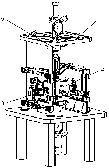
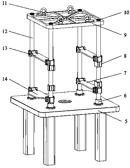
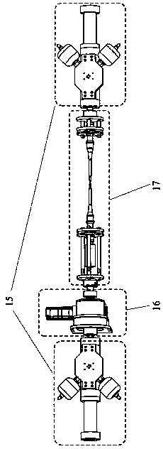
[0051] see Figure 1 to Figure 19 As shown, the high-temperature ultrasonic fatigue in-situ testing instrument and testing method of the present invention are composed of an overall frame module, a mechanical loading module, a high-temperature loading module and an in-situ monitoring module. Among them: the overall frame module is used for precise positioning of each functional module, while providing stable support and effective vibration isolation; the mechanical loading module is used to simultaneously apply static tensile / compressive loads to both ends of the tested sample, and apply ultrasonic fatigue loads according to the test requirements , and can achieve precise axial indexing; the high-temperature loading module is used to apply high-temperature loads to the tested sample; the in-situ monitoring module ...


PUM


Abstract

The invention relates to a high-temperature ultrasonic fatigue in-situ test instrument and a test method, and belongs to the field of a precise scientific instrument. The instrument consists of an integrated frame module, a mechanical loading module, a high temperature loading module and an in-situ monitoring module, wherein the integrated frame module is used for accurately positioning each functional module and simultaneously providing stable support and effective vibration isolation; the mechanical loading module is used for synchronously exerting static stretching or compression load on two ends of a tested sample and exerting an ultrasonic fatigue load according to test needs and is capable of realizing axial precise positioning; the high temperature loading module is used for exerting a high temperature load on the tested sample; and the in-situ monitoring module is used for performing in-situ monitoring on the surface deformation damage and the internal damage defect of the tested sample. The synchronous representation and three-dimensional reconstruction for the defect information of the tested sample can be implemented from inside to outside and from the exterior to the interior. The high-temperature ultrasonic fatigue in-situ test instrument has the characteristics that the load environment is complex, the test precision is high and meanwhile the material mechanical behavior and deformation damage mechanism can be dynamically monitored.

Description

technical field [0001] The invention relates to the field of precision scientific instruments, in particular to a high-temperature ultrasonic fatigue in-situ testing instrument and a testing method. Under vacuum or inert gas atmosphere, the high-temperature loading of the tested material sample can be realized, and at the same time, the simultaneous characterization and three-dimensional reconstruction of the defect information of the tested sample can be realized from the inside to the outside, from the surface to the inside. It provides a reliable method for the research of fatigue performance and deformation damage mechanism of materials in aerospace, equipment manufacturing and other fields under high temperature and ultrasonic load. Background technique [0002] Combined with in-situ monitoring methods, the mechanical-thermal coupling fatigue test is an important means to obtain the service performance of materials at high temperatures and explore the evolution law of t...

Claims


Application Information

Patent Timeline
Patent Type & Authority Applications(China)
IPC IPC(8): G01N3/18
CPCG01N3/18G01N2203/0003G01N2203/0017G01N2203/0019G01N2203/0048G01N2203/0055G01N2203/0073G01N2203/0226G01N2203/0244G01N2203/0647
Inventor 赵宏伟赵久成张世忠徐利霞万杰周水龙靖旭方宇明陈俊先秦学志王赵鑫
Owner JILIN UNIV
Why Eureka
Try Eureka