
Wireless charging and communication coil fixed connection assembly of active implantable medical device

An implantable medical and wireless charging technology, which is applied to measuring devices, measuring device casings, components of electrical measuring instruments, etc., can solve the problem of high requirements for storage time and storage conditions, inconvenient disassembly of the soft connection board, and damage to the device. problem, to achieve the effect of easy disassembly and assembly

Pending Publication Date: 2019-11-12
TSINGHUA UNIV
View PDF0 Cites 0 Cited by
  • Summary
  • Abstract
  • Description
  • Claims
  • Application Information

AI Technical Summary

Problems solved by technology

[0004] No matter which connection process is used above, it is inevitable to use the flexible connection board, and since the flexible connection board is welded and connected with the coil or the hard circuit board, and then glued and fixed, the flexible connection board is not easy to disassemble. Unqualified disassembly is likely to cause damage to the entire device
In addition, after the flexible connecting board is welded, in order to ensure the welding quality, the requirements for storage time and storage conditions are relatively high

Method used


Image

  • Wireless charging and communication coil fixed connection assembly of active implantable medical device
  • Wireless charging and communication coil fixed connection assembly of active implantable medical device
  • Wireless charging and communication coil fixed connection assembly of active implantable medical device

Examples


Embodiment 1

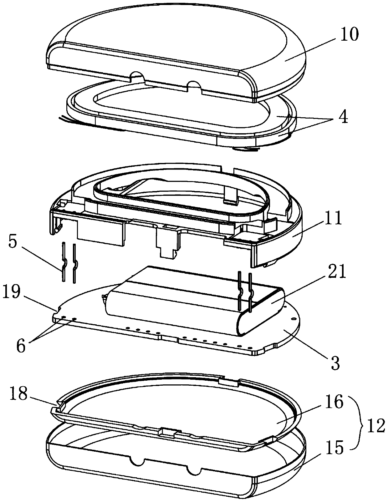
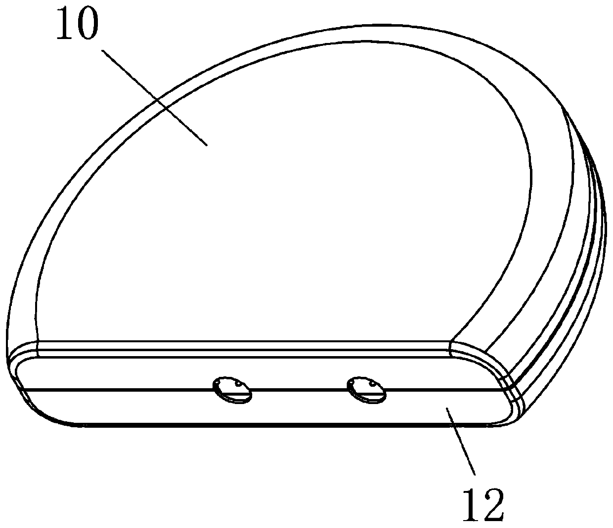
[0063] Such as figure 1 and Figure 9 As shown, it is a specific embodiment of the coil bracket assembly of an active implantable medical device, including: a frame 11, an upper cover 10 and a lower cover 12, wherein the lower cover 12 includes a detachable outer cover 15 and The inner lining 16, the outer jacket 15 and the inner lining 16 are fixedly connected by glue bonding.

[0064] The upper cover 10 has a groove for accommodating the frame 11 and is detachably fixedly connected to the outer wall of the frame 11 .

[0065] The lower cover 12 is fastened and docked with the upper cover 10, and is fixedly connected with the frame 11 by clamping, wherein, the outer cover 15 of the lower cover 12 is fastened butted with the upper cover 10, and the inner surface of the lower cover 12 The liner 16 is detachably and fixedly connected in the outer casing 15 for clipping the frame 11 . The upper cover is arranged on the side of the second accommodation hole for accommodating th...

Embodiment 2

[0075] Such as figure 1 Shown is a specific embodiment of an active implanted medical device, including: a coil bracket assembly, a hard circuit board 3 , a coil 4 , a rigid connector 5 and a battery 21 . Wherein, the coil bracket assembly is used to accommodate the hard circuit board 3 , the coil 4 , the rigid connector 5 and the battery 21 .

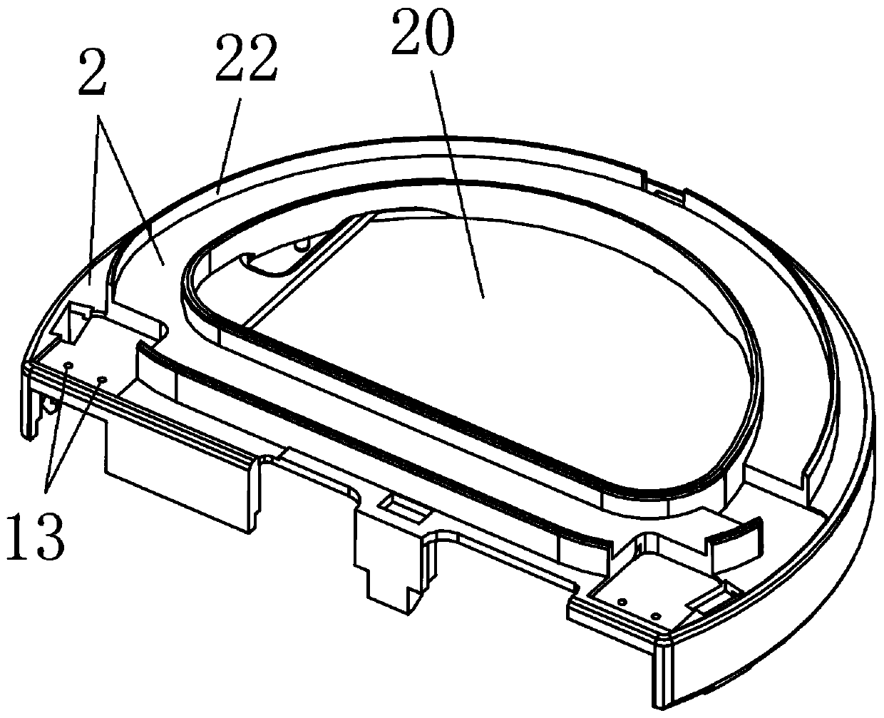
[0076] The coil bracket assembly adopts the coil bracket assembly described in Embodiment 1, which has two detachable layers, wherein the first layer has a first receiving groove 1 for accommodating the hard circuit board 3, and the second layer There is a second accommodating slot 2 for accommodating the coil 4 inside. Specifically, such as Figure 9 As shown, the coil bracket assembly includes: an upper cover 10 , a frame 11 and a lower cover 12 . The upper cover 10 has a groove for accommodating the frame 11, and is detachably fixedly connected to the outer wall of the frame 11; the frame 11 is fixedly connected between the upper...

Embodiment 3

[0084] This embodiment provides a rigid connector for an active implanted medical device, which is used to electrically connect a hard circuit board and a coil in an active implanted medical device, such as Figure 10 , Figure 11 As shown, it includes: a first connection section 7 and a second connection section 9 .

[0085] The first connecting section 7 is located at the lower end, is a straight section, is fixed through the insertion hole 6 of the hard circuit board 3 inserted into the active implanted medical device, and is electrically connected with the hard circuit board 3 .

[0086] The second connection section 9 is located at the other end relative to the first connection section 7: the upper end is a straight section, such as Figure 12 , Figure 13 As shown, the second connection section 9 is fixed by being inserted into the coil bracket assembly in the active implanted medical device, and extends through the coil bracket assembly to the second layer of the coil...


PUM


Abstract

The invention provides a wireless charging and communication coil fixed connection assembly of an active implantable medical device, which comprises a frame, wherein the frame comprises a first accommodating groove, a second accommodating groove and a connecting hole; the connecting hole penetrates the frame and is used for penetration of a rigid connecting piece so that the rigid connecting pieceis electrically connected with a hard connecting plate and a coil; the connecting hole is connected with the rigid connecting piece through a positioning structure. The coil fixed connection assemblyis provided with the frame, a hard circuit board and the coil are respectively fixed on the front side and the back side of the frame, and the frame is provided with the connecting hole for penetration of the rigid connecting piece and fixing the rigid connecting piece, so that two ends of the rigid connecting piece can be electrically connected with the hard circuit board and the coil conveniently, thereby avoiding the defect that the hard circuit board and the coil are electrically connected through a flexible connecting piece in the prior art, therefore, the connected hard circuit board and the coil are convenient to disassemble and assemble for a plurality of times, and damage of the whole device can not be caused easily.

Description

technical field [0001] The invention relates to the technical field of implantable medical devices, in particular to a wireless charging and communication coil fixed connection assembly for an active implantable medical device. Background technique [0002] Human body active implantable medical device (Active Implantable Medical Device, AIMD) is a medical device installed inside the user's body. This device has batteries, hard circuit boards (with sensors, chips and other components) inside, and AIMD relies on The corresponding therapy can be realized through the set programs and operating parameters, and these operating parameters can adopt different settings according to the user's disease conditions. Because of the different causes and conditions of users, the active implantable medical devices installed in different users generally have different operating states. These operating states are reflected in the battery voltage, running time, power, Current magnitude, freque...

Claims


Application Information

Patent Timeline
Patent Type & Authority Applications(China)
IPC IPC(8): G01R31/28G01R31/00G01R1/04
CPCG01R31/2832G01R31/00G01R1/0408G01R1/0416
Inventor 王伟明李路明文雄伟
Owner TSINGHUA UNIV
Learn More