Coaxial cavity duplexer

A technology of duplexer and coaxial cavity, which is applied to waveguide-type devices, electrical components, circuits, etc., can solve the problems of large occupied area and unfavorable system integration, and achieve the effect of easy design, simple and compact structure, and good filtering characteristics.

Pending Publication Date: 2019-11-12
SOUTH CHINA UNIV OF TECH
View PDF0 Cites 0 Cited by
  • Summary
  • Abstract
  • Description
  • Claims
  • Application Information

AI Technical Summary

Problems solved by technology

However, traditional cavity duplexers generally adopt a side-by-side structure, occupying a large area, which is not conducive to system integration, and has become one of the main bottlenecks restricting system miniaturization.

Method used


Image

  • Coaxial cavity duplexer
  • Coaxial cavity duplexer
  • Coaxial cavity duplexer

Examples


Embodiment Construction

[0014] The present invention will be further described below in conjunction with specific examples.

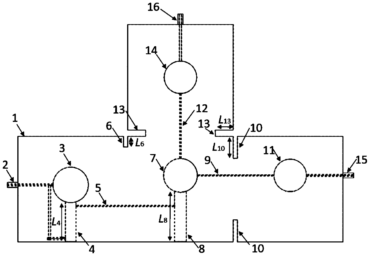
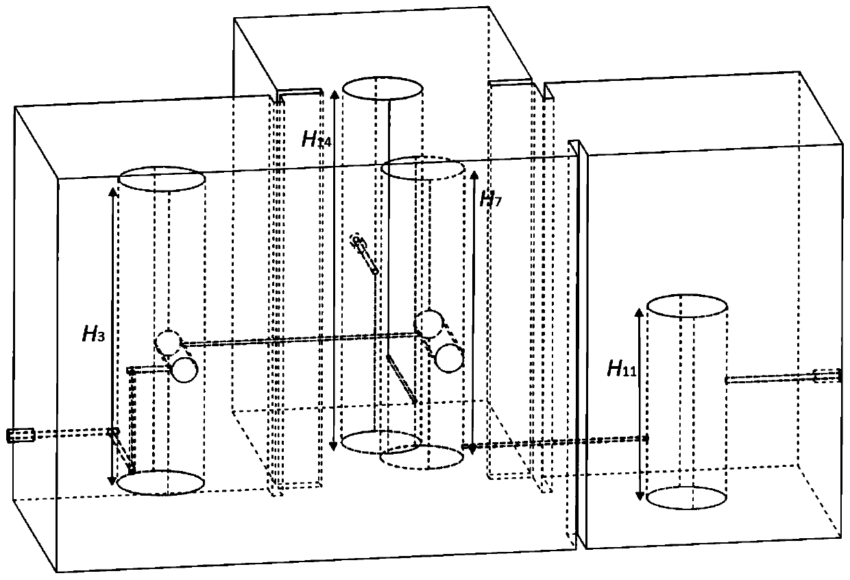
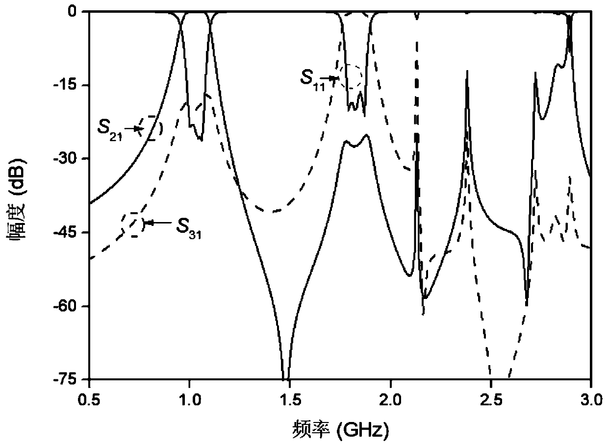
[0015] Such as figure 1 and figure 2 As shown, the coaxial cavity duplexer provided in this embodiment includes a closed metal cavity 1 and three input and output ports, which are respectively the first input and output port 2, the second input and output port 15, and the third input and output ports. Output port 16; the entire shape of the metal cavity 1 is in the shape of a "convex", and there are four resonant cavities in total, each of the three protruding parts is one, and the remaining middle part is one, and the one in the middle part is The resonant cavity is the second-order coaxial resonant cavity, the resonant cavity located on the left side of the second-order coaxial resonant cavity is the first-order coaxial resonant cavity, and the resonant cavity located on the right side of the second-order coaxial resonant cavity is the right The third-order coaxial resona...


PUM


Abstract

The invention discloses a coaxial cavity duplexer; the coaxial cavity duplexer comprises a metal cavity and input and output ports; the metal cavity is in a convex shape, and is divided into four resonant cavities, wherein three resonant cavities protrude outwards respectively, and the left one is located in the middle; the resonant cavity in the middle part is a second-order coaxial resonant cavity, and the resonant cavities on the left side, the right side and the back part of the second-order coaxial resonant cavity are a first-order coaxial resonant cavity, and third-order coaxial resonantcavities on the right side and the back part; the first-order coaxial resonant cavity and the second-order coaxial resonant cavity are shared resonant cavities and have double-frequency characteristic; the third-order coaxial resonant cavities on the right side and the back part are single-frequency resonant cavities, and single-frequency-band parts thereof are taken out; and the four resonant cavities are coupled through a coupling resonance window; and the three input and output ports are coaxial feeder lines which are all extend into a vertical metal cylinder of the first-order coaxial resonant cavity and the resonant rods of the third-order coaxial resonant cavities on the right side and the back part. The coaxial cavity duplexer is compact in structure, miniaturized, easy to tune andhigh in selectivity.

Description

technical field [0001] The invention relates to the technical field of microwave communication, in particular to a coaxial cavity duplexer. Background technique [0002] With the rapid development of wireless communication technology, the design of microwave systems is becoming more and more complex, the requirements for circuit indicators are getting higher and higher, the functions of circuits are more and more, the size of circuits is required to be smaller and smaller, and the design cycle is getting shorter. come shorter. Today's wireless communication systems require microwave devices with higher performance, smaller size, and lower loss. Therefore, in order to use as few devices as possible to meet the requirements of the communication network, the two filters can be integrated into a duplexer. The duplexer is a relatively special bidirectional three-terminal filter, which is the key device for the whole machine to complete the transceiver function. Its function is ...

Claims


Application Information

Patent Timeline
Patent Type & Authority Applications(China)
IPC IPC(8): H01P1/208H01P1/202
CPCH01P1/202H01P1/208
Inventor 谢雅陈付昌
Owner SOUTH CHINA UNIV OF TECH
Why Eureka
Try Eureka